Table of Contents
SpeedFan can read supported temperature, voltage, fan-speed, and drive S.M.A.R.T. data, and it can control fans on some motherboards. Start by using it only as a monitor. Fan-control support is hardware-specific, and changing the wrong PWM channel can slow or stop a critical fan.
Check compatibility before using SpeedFan
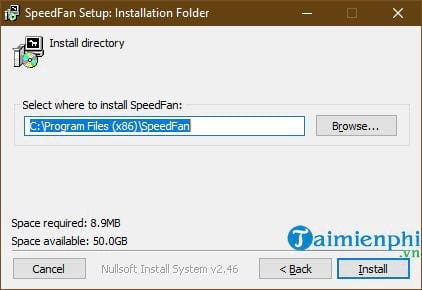
Download SpeedFan only from the developer's official download page. The current official release listed there is 4.52. Because SpeedFan depends on particular motherboard monitoring chips and firmware behavior, a modern PC may show incomplete, mislabeled, or non-controllable sensors.
Laptop fans are commonly managed by an embedded controller and may not be available to SpeedFan. For a current desktop or laptop, prefer the fan controls in BIOS or UEFI, or the computer or motherboard manufacturer's utility, when those options are available.
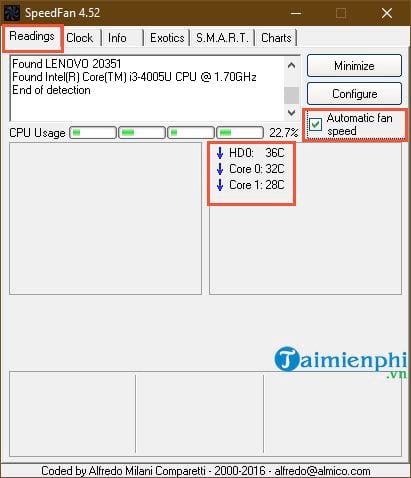
Read temperatures and fan speeds
- Open SpeedFan and allow its hardware scan to finish.
- On the Readings tab, note the listed temperatures, fan RPM values, and CPU utilization.
- Do not assume labels such as Temp1, Temp2, or Fan1 identify a specific component correctly.
- Run a controlled workload and observe which temperature and RPM values change.
- Compare the result with BIOS hardware monitoring or a second reputable utility.

An impossible fixed temperature or a fan value of zero may be an unsupported sensor rather than a failed component. Confirm the physical fan is spinning before troubleshooting software.
Understand the main tabs
Readings
This is the primary monitoring page. Automatic fan speed should remain off until every relevant temperature source and fan channel has been identified and a safe curve has been configured.
Clock
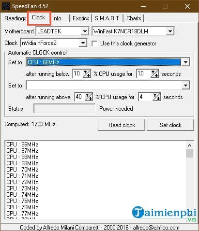
The Clock page contains legacy clock-control functions for supported hardware. It is unrelated to normal fan monitoring and should be left unchanged unless you have board-specific documentation and a recovery plan.
Info and Exotics
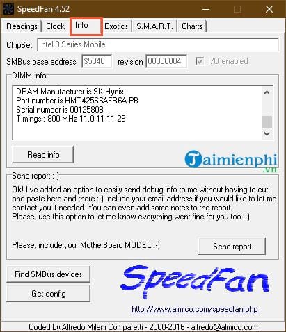
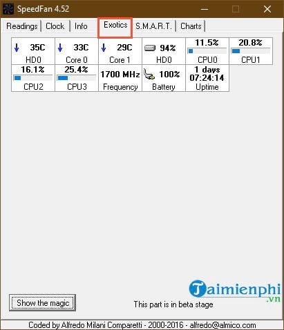
The Info tab reports detected hardware and provides diagnostic information. The Exotics tab summarizes selected readings. Review any report before sharing it because hardware reports can include identifiers.
S.M.A.R.T.
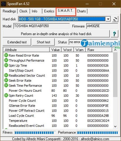
The S.M.A.R.T. page can display attributes exposed by a supported storage device. It is not a guarantee that a drive will not fail and does not replace a current backup. NVMe and USB storage support may be incomplete.
Charts
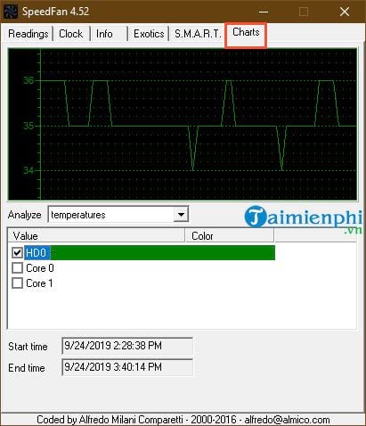
Use Charts to watch a selected temperature, fan speed, or voltage over time. A trend under a repeatable workload is more useful than one instantaneous value.
Configure fan control only after verification
Select Configure and review the Temperatures, Fans, and Speeds pages. Rename verified items so their purpose is clear, such as CPU Fan or Rear Case Fan. Leave unknown rows disabled rather than guessing.
The Advanced page may expose PWM modes for a detected Super I/O chip. These settings are motherboard-specific. Changing a PWM mode can hand control to software, leave it under firmware control, or disable useful automatic behavior. Do not change it unless the board and channel are positively identified.
Find a safe minimum speed
If a verified channel is controllable, reduce it only in small steps while physically watching the correct fan and its RPM reading. Stop well above the point where the fan stalls or fails to restart. Restore the original value immediately if RPM disappears, temperature rises unexpectedly, or the wrong fan changes.
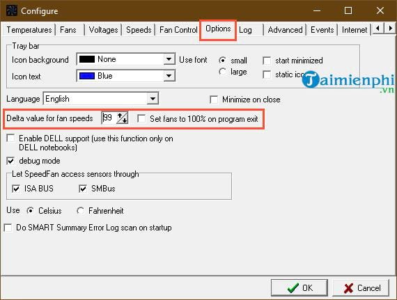
Do not copy a universal minimum, maximum, Delta, or “100% on exit” value from another computer. Fan motors, headers, sensor mappings, and cooling requirements differ.
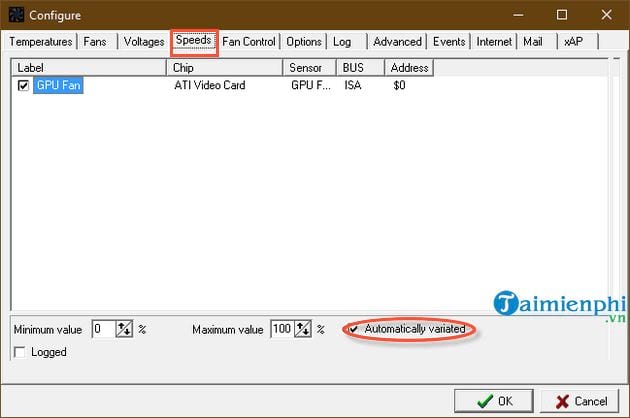
Map a temperature to the correct fan
On the Temperatures page, associate a verified component sensor only with fans that cool that component. Use the hardware manufacturer's operating limit and the cooling system's normal behavior to set targets; there is no universal desired temperature for all CPUs or GPUs.
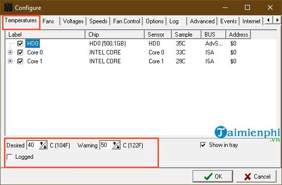
After configuring a curve, enable automatic control and watch the system through idle, moderate load, and sustained load. Confirm that every fan speeds up as expected and returns to normal afterward. Keep BIOS fan protection enabled where possible.
Safer alternatives for unsupported hardware
If SpeedFan cannot identify the board, reports implausible sensors, or cannot control a fan reliably, stop using its control functions. Set the fan curve in BIOS or use the manufacturer's current utility. For temperature monitoring alone, compare PC temperature-monitoring applications or follow the guide to checking CPU, GPU, drive, and RAM temperatures.
Fan control should fail safely. A quieter computer is not worth a curve that can stop a fan, hide a sensor, or depend on an unsupported utility starting correctly with Windows.
Related Articles
 SpeedFan - PC Hardware Monitoring Utility6 minutes read
 How to Use Speedfan to Check CPU Temperature, Fan Speed, Computer3 minutes read
 How to Use SpeedFan to Check and Adjust CPU Fan Speed4 minutes read
 How to Check CPU Temperature Using Hwmonitor6 minutes read
 How to Check the Computer's CPU Temperature?3 minutes read
 The Ideal GPU Temperature Explained8 minutes read
Reader Comments 0
Sign in with email or Google to join the discussion.