How to Create a Basic Laptop Design in the Solidworks CAD Program
Have you ever wondered how 3D models are designed and wanted to try to model yourself? This article will teach you the basic skills needed to model a basic laptop design as well as many other shapes Open the SolidWorks program.
Table of Contents
Part 1 of 3:
Creating the Basic Shape
- Open the SolidWorks program.
- Select "new part" in the new SolidWorks document menu and then press 'OK.'
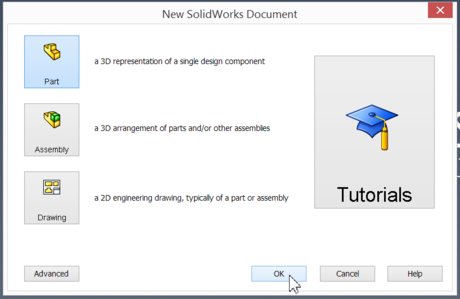
- Select "new part" in the new SolidWorks document menu and then press 'OK.'
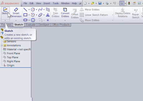
- Set up the first sketch.
- Click on Sketch at the top left corner of the screen.
- Select any of the three planes shown (The top plane was chosen in this example).
- Begin the first sketch.
- Use the line tool at the top left side of the screen to create a rectangle.
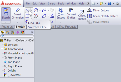
- This rectangle will be used as the base of the laptop.

- Use the line tool at the top left side of the screen to create a rectangle.
- Begin to dimension the rectangle and place it in a convenient position.
- Select the lower line of the rectangle and hold the 'Ctrl' button on the keyboard while selecting the predefined origin of this shape.

- By simultaneously having these two objects selected, a relation is able to be made.
- Select the lower line of the rectangle and hold the 'Ctrl' button on the keyboard while selecting the predefined origin of this shape.
- Add the first relation. Make sure the two objects are still selected.
- The left side of the screen's properties menu shows which lines are selected and contains a small sub-menu that says 'Add Relations.' The Midpoint button must be selected from this menu.
- The midpoint button will center the bottom line with the origin as well as move it to the origin.

- Dimension the rectangle.
- Select the "Smart Dimensions" button at the top left side of the screen.

- Then, click on two opposite corners of the rectangle to dimension the diagonal length.

- The length used in this design is 15 inches (38.1 cm).

- Select the "Smart Dimensions" button at the top left side of the screen.
- Dimension the top and bottom of the rectangle.
- This dimension is done using a very similar method as the previous step.
- Instead of selecting two opposite corners, the top and bottom lines are selected and dimensioned.

- The vertical length used was 8 inches (20.3 cm).

- Extrude the rectangle.
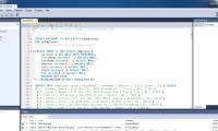
- Now that the rectangle is dimensioned, the Exit Sketch button at the top left of the screen is selected and the Features tab under that button is clicked.

- In the Features menu, click Extrude Boss/Base button after selecting your sketch from left menu.


- In this example, Sketch 2 is selected.
- From here, the rectangle that was made can be extruded to any desired length and the green check mark can be selected to confirm.

- In this example, the rectangle was extruded by 0.3 inches (0.8 cm).

- Now that the rectangle is dimensioned, the Exit Sketch button at the top left of the screen is selected and the Features tab under that button is clicked.
Part 2 of 3:
Adding the Hinges
- Set up the Sketch for the hinges of the laptop.
- The next step is to create the hinges for the laptop screen.
- First, select the side face of the laptop.

- Then click the sketch tab at the top left of the screen. In the Sketch menu, select the "Sketch Button".

- When the sketch is selected to be on the plane specified, click on the "Space Bar" on the keyboard to open up another menu.
- The orientation menu box will appear in which you are able to change the views of the shape. Click on the picture of an arrow sticking out of a flat plane (the normal button). The normal button is used to change the orientation to a view that is normal to the plane selected.

- When the normal plane is being viewed, the sketch for the hinges can begin.

- Begin the sketch for the hinges of the laptop.
- In this sketch, create a rectangle (in a similar fashion to the first sketch) on the left side of the plane as shown.

- In this sketch, create a rectangle (in a similar fashion to the first sketch) on the left side of the plane as shown.
- Dimension and add relations to the rectangle created for the hinges.
- Like before, this rectangle needs to be dimensioned and certain parts of it need to be given relations.

- Below, the edge of the previous rectangle and the left side of the new rectangle are both selected. The relation added to them is co-linear (similarly to the last sketch). The same is done to the bottom of the rectangle and the top of the previous rectangle.

- When that is done, the width and height of this rectangle is decided by using the smart dimension button as done before.

- The dimension result should look something like shown below.


- When they are completed, you can select Exit Sketch.

- Like before, this rectangle needs to be dimensioned and certain parts of it need to be given relations.
- Extrude the hinge sketch.
- The hinge sketch can now be extruded in the same way as was done in the previous sketch.

- The direction of the extrusion can be changed with the button shown below.


- 'Through all' should also be selected from the left side menu in order to have the hinge extruded up to the other end of the laptop base.

- When everything is confirmed, select the green check box.


- The hinge sketch can now be extruded in the same way as was done in the previous sketch.
- Setup the sketch used to cut away parts of the extruded hinge.
- Select the inside face of the hinge and create a sketch.

- When the sketch is created, change the orientation to the normal face of the sketch.

- In this sketch, the cuts are going to be created to turn the long rectangle into two normal sized hinges.

- The rectangles that will make the cut should look like the picture shown below.


- Select the inside face of the hinge and create a sketch.
- Edit sketch used to cut away parts of the extruded hinge.
- A horizontal line should be created at the center of the object.


- When this line is created, the 'Trim Entities' (also around the top and left of the screen) button should be selected. This button allows you to trim away certain parts of the sketch.


- In this example, the entire bottom of the sketch was trimmed away as well as the lines in between the rectangles.

- When this is complete, the sketch is finished and the Exit Sketch button can be selected.

- A horizontal line should be created at the center of the object.
- Use the Extrude Cut command with the sketch that was just created.
- The features tab should be selected and the 'Extruded Cut' button should be pressed.

- This will cut through the piece and create the two desired hinges.

- The picture below shows the complete hinges.

- The features tab should be selected and the 'Extruded Cut' button should be pressed.
Part 3 of 3:
Adding the Details
- Create the screen part of the laptop. A very similar method to creating the hinges is used when creating this piece.
- The side plane is selected for the sketch and the orientation is changed to a view normal to the plane.

- A rectangle is then created and dimensioned to the shown specifications.


- The "Exit Sketch" button can be selected after this is done.

- The screen piece is then extruded exactly as the hinges were.
- This model now somewhat looks like a laptop as shown below.

- The side plane is selected for the sketch and the orientation is changed to a view normal to the plane.
- Create a cutout of the touch pad. This cutout will be made using the same commands as shown before.
- The top plane of the first rectangle is selected for the sketch and a rectangle is drawn as shown.


- In this example, the touch pad was extrude cut 0.1 inches (0.3 cm) into the material after the Exit Sketch button was selected.


- The top plane of the first rectangle is selected for the sketch and a rectangle is drawn as shown.
- Create the cutout of the keyboard.
- The cut-out for the keyboard is also made in a very similar way with the shown dimensions.


- The cut-out for the keyboard is also made in a very similar way with the shown dimensions.
- Create the cutout for the screen.
- The screen is made similarly too (on the inside plane of the screen extrude) with the shown dimensions below.


- The screen is made similarly too (on the inside plane of the screen extrude) with the shown dimensions below.
- Finished.
- Now you are capable of completing more complex designs and can apply what you learned in this tutorial on other projects!

- Now you are capable of completing more complex designs and can apply what you learned in this tutorial on other projects!
Was this article helpful?
Your feedback helps us improve.
Related Articles
 Macromedia Flash - Program flash download design4 minutes read
 The father used 3D printing technology to drive Aventador supercar to be donated to his son3 minutes read
 Basic C program structure3 minutes read
 How to create a database in MySQL6 minutes read
 New design for HP laptop4 minutes read
 Create Label in Word 20103 minutes read
Reader Comments 0
Sign in with email or Google to join the discussion.