TMG 2010 ISP Redundancy Feature (Part 1)
Network Administration - One of the notable features in TMG Firewall 2010 version is the ISP load balancing capability. If you've ever used ISA Firewall, you may find that the ability to support multiple ISPs is an essential feature since ISA 2004 was released. And this feature will be integrated in the upcoming TMG Firewall 2010 version.
In Part 1 of this article we will configure the virtual system and TMG Firewall communications.
Before understanding the multi-ISP feature of TMG, we will generalize some basic points of TMG Firewall:
Multi-ISP support allows us to use ISP in one of two ways:
Failover only (Status change only). In this mode an ISP will always be used until it is no longer usable. When this situation occurs, connections will be forwarded to the secondary ISP. This is a good choice when using a high-speed link and a low-speed link, in addition we will not have to spend on broadband but only use it when needed.
Failover and load balancing (Forward and load balancing ). In this mode both links will be used. We have an option to set the capacity for each link, so you won't have to use both links at the same time. If one of the links fails every connection will switch to the link that is online.
Multi-ISP support for virtual environments
Next we will perform some operations so that the virtual environment also receives Multi-ISP support. In this article we will use VMWare Workstation, and you can use Windows Virtual PC, ESX Server or Microsoft Hyper-V. There is not much difference between these software because they all use the same principles.
First we will start with the basic virtual network schema. We will use four virtual networks or virtual transitions, each of which belongs to a different physical or virtual Ethernet distribution segment.
1. RRAS1 and RRAS2 nodes display the default Gateway we will use when configuring ISP for the entire system. Therefore, RRAS1's internal IP address displays the ISP's default Gateway first, and RRAS2's internal IP address represents the second ISP's default Gateway. Our test system is completely different, in that the Internet connection is made through Bridged Network, so the external interfaces on RRAS1 and RRAS2 use the same Gateway.
2. We are using dedicated NICs on TMG Firewall for each ISP. This is not necessary, but in the next section we will configure ISP connections when there is no dedicated NIC.
3. We can create similar network segments with some other virtual tools (such as Windows Virtual PC, ESX and Hyper-V) that support similar network segmentation methods.


Configure network interface on TMG Firewall


In Part 1 of this article we will configure the virtual system and TMG Firewall communications.
Before understanding the multi-ISP feature of TMG, we will generalize some basic points of TMG Firewall:
- While the term used for this feature is multi-ISP support, to make it more clear we can call this support dual ISP because it only allows up to 2 ISPs.
- There will have to be a NAT relationship between the destination network and the source network, so if you are using a routing relationship on any of TMG Firewall's Protected Network, they cannot take advantage of many ISPs.
- Each ISP connection needs to connect to a default gateway on a different network ID such as another ISP, both default gateways cannot exist on the same network ID (that is, external network addresses on TMG Firewall also cannot have the same network ID).
- It is not possible to use DHCP to get the addresses of external interfaces, if you are using a home user ISP connection, you cannot support multi-ISP.
- You can store both ISP connections on one or two NICs. In this article we will explore the configuration of 2 NICs, each ISP connection is displayed by its own external interface.
- Handling network transfers needs to be set on (on) or off (on) on both NICs, if either of these NICs is open and the NIC is turned off, the transfer processing will be turned off on the NIC is on.
Multi-ISP support allows us to use ISP in one of two ways:
Failover only (Status change only). In this mode an ISP will always be used until it is no longer usable. When this situation occurs, connections will be forwarded to the secondary ISP. This is a good choice when using a high-speed link and a low-speed link, in addition we will not have to spend on broadband but only use it when needed.
Failover and load balancing (Forward and load balancing ). In this mode both links will be used. We have an option to set the capacity for each link, so you won't have to use both links at the same time. If one of the links fails every connection will switch to the link that is online.
Multi-ISP support for virtual environments
Next we will perform some operations so that the virtual environment also receives Multi-ISP support. In this article we will use VMWare Workstation, and you can use Windows Virtual PC, ESX Server or Microsoft Hyper-V. There is not much difference between these software because they all use the same principles.
First we will start with the basic virtual network schema. We will use four virtual networks or virtual transitions, each of which belongs to a different physical or virtual Ethernet distribution segment.
- Bridged : This is the network in use in the company's network. Virtual NICs will be connected to this network, there will be a number of valid IP addresses on the network in use and use this network to connect to the Internet.
- VMNet3 : This is a virtual switch that represents the Ethernet segment that connects the TMG Firewall to the ISP first.
- VMNet4 : This is a virtual switch that represents the Ethernet segment that connects the TMG Firewall to the second ISP.
- VMNet2 : This is a virtual switch that represents the Ethernet segment that connects the TMG Firewall to the default Internet.
- RRAS1 : This is a Windows Server 2003 virtual machine with RRAS service configured as a NAT server. The external interface of this virtual machine is connected to Bridged Network, and internal communication is connected to VMNet3, connecting the NIC on the TMG firewall used for RRAS1 ISP to the Windows 2003 RRAS NAT server.
- RRAS2 : This is a Windows Server 2003 virtual machine with RRAS service configured as a NAT server. The external interface is connected to Bridged Network and internal communication is connected to VMNet4, connecting the NIC on RRAS2 ISP TMG Firewall using RRAS Windows NAT server.
- TMG Firewall : TMG Firewall has three NICs. One connection to VMNet3 (VMNet3 connects this NIC to RRAS1 ISP), one connects to VMNet4 (connected to RRAS2 ISP), and the other NIC connects to VMNet2 (connecting TMG Firewall to the default Internet).
- DC : Is a Windows Server 2003 Domain Controller for the msfirewall.org domain. TMG Firewall belongs to this domain and is connected to VMNet2.
1. RRAS1 and RRAS2 nodes display the default Gateway we will use when configuring ISP for the entire system. Therefore, RRAS1's internal IP address displays the ISP's default Gateway first, and RRAS2's internal IP address represents the second ISP's default Gateway. Our test system is completely different, in that the Internet connection is made through Bridged Network, so the external interfaces on RRAS1 and RRAS2 use the same Gateway.
2. We are using dedicated NICs on TMG Firewall for each ISP. This is not necessary, but in the next section we will configure ISP connections when there is no dedicated NIC.
3. We can create similar network segments with some other virtual tools (such as Windows Virtual PC, ESX and Hyper-V) that support similar network segmentation methods.
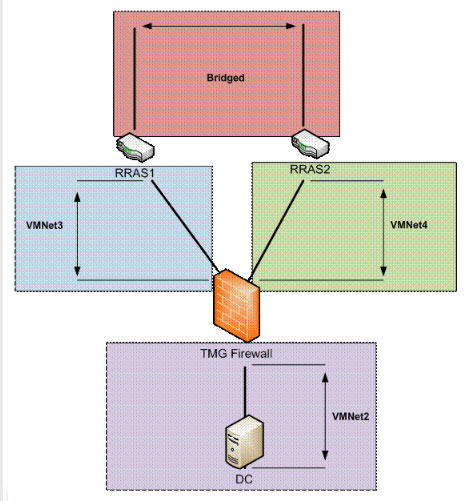
Figure 1
Now that we have created a virtual network structure, we will then check the IP address scheme. The IP address used in this example is shown in Figure 2. Note that TMG RRAS1 ISP NIC uses the internal communication of RRAS1 as its default Gateway. In addition, the network segment RRAS1 belongs to the network ID 10.0.1.0/24 , and the RRAS2 network segment belongs to the network ID 10.0.2.0/24 .
TMG Firewall's default intranet is in network ID 10.0.0.0/24 , and DC on the local intranet uses TMG Firewall as its default Gateway.
TMG Firewall's default intranet is in network ID 10.0.0.0/24 , and DC on the local intranet uses TMG Firewall as its default Gateway.
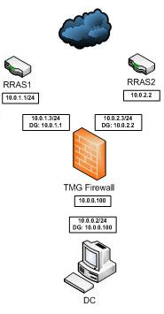
Figure 2
In this article we will explore ISP load balancing features. Therefore we will pay attention to the method TMG Firewall performs load balancing. Basically, TMG Firewall will check the source address (workstation) and destination address (server) and create a hash value, which is then described as a value between 1 and 100. All prices Hash rules can be distributed evenly in this range. After calculating this value, TMG Firewall will check the traffic assigned to each ISP.
For example, suppose ISP1 is assigned 75% of the load, and ISP2 is assigned 25%. If the Hash value is 30, the connection will switch to ISP1, because that Hash value is lower than the value assigned to the preferred connection. If the hash value is 80, the connection will be forwarded to ISP2 because this value is higher than the value assigned to the preferred connection.
For example, suppose ISP1 is assigned 75% of the load, and ISP2 is assigned 25%. If the Hash value is 30, the connection will switch to ISP1, because that Hash value is lower than the value assigned to the preferred connection. If the hash value is 80, the connection will be forwarded to ISP2 because this value is higher than the value assigned to the preferred connection.
In short, we need:
- Check the load on the preferred connection (as a percentage).
- If the hash value is lower than the traffic then the preferred connection is used.
- If the hash value is higher than the traffic then the secondary connection will be used.
Of course, if we install both ISP connections as 50% then half the hash value will be less than 50 and half will be higher than 50, so all connections will be divided equally between ISPs.
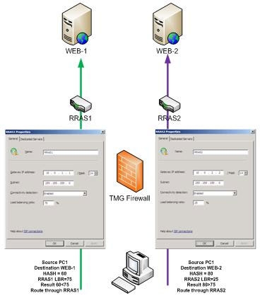
Figure 3
Configure network interface on TMG Firewall
In Figure 4 we can see the network interfaces configured on the TMG Firewall used in this example. LAN interface is connected to VMNet2, WAN interface is connected to VMNet3 and WAN2 connected to VMNet4.
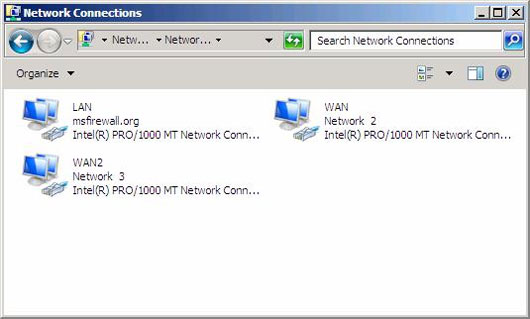
Figure 4
The NIC WAN interface was originally configured on the TMG Firewall, so it was granted a default Gateway before starting the TMG Firewall configuration. In Figure 5, we can see that it has been assigned an effective IP address for ISP RRAS1 and receives the default Gateway as the internal IP address of the RRAS1 virtual machine (this will be the default Gateway of the real ISP in system). In addition, we need to access the Advanced TCP / IP settings and turn off the Automatic metric feature. Microsoft recommends doing so so that the ISP Redundancy feature works stably. However, we need to install a metric Manual . The only requirement that we need to comply with is that prioritizing communication settings with a lower metric than communication is not a priority. In Figure 5, priority communication has been set using metric 1.
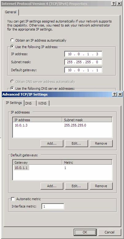
Figure 5
Figure 6 shows the IP address information for the non-preferred ISP (ISP RRAS2). This interface is set using a metric 2.
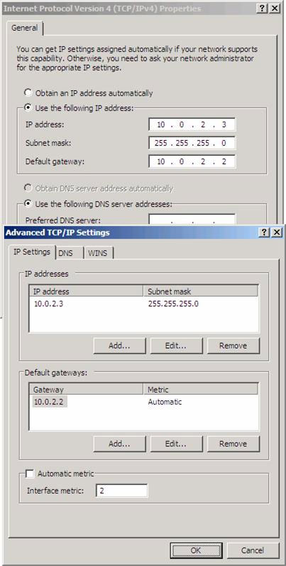
Figure 6
Windows does not allow the assignment of two default Gateway on the same machine. However, TMG Firewall's ISP Redundancy feature allows us to break this rule, so we just need to click Yes when we see the warning shown in Figure 7.
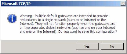
Figure 7
Before installing, we need to check which communication will be used. We have configured TMG Firewall and created an open rule. When using the tracert command we will know that priority communication will be used.
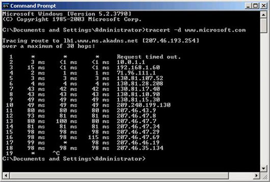
Figure 8
Here is the order to perform to configure the communication:
In this first part of this series on TMG Firewall's ISP Redundancy feature, we have a brief overview of virtual network structure and some information about ISP selection method. We then configured communication and some notes when configuring network interfaces to connect to each ISP. In the next section, we will configure the ISP load balancing feature and check whether it really works by testing from a workstation and checking the TMG Firewall Log files and a Number of traces on Netmon.
- Create an initial virtual machine with two NICs - internal and ngap.
- Assign an IP address for external communication and internal communication.
- Install TMG Firewall software.
- Confirm that the installation was successful.
- Turn off the TMG virtual machine and install a third virtual NIC to support the second ISP link.
- Third virtual NIC configuration after restarting the virtual machine.
- Restart the virtual machine after configuring the IP address on the third interface.
- This is not a method proposed by Microsoft but it has been tested and works well.
In this first part of this series on TMG Firewall's ISP Redundancy feature, we have a brief overview of virtual network structure and some information about ISP selection method. We then configured communication and some notes when configuring network interfaces to connect to each ISP. In the next section, we will configure the ISP load balancing feature and check whether it really works by testing from a workstation and checking the TMG Firewall Log files and a Number of traces on Netmon.
Share by
Kareem Winters
Update 26 May 2019