Table of Contents
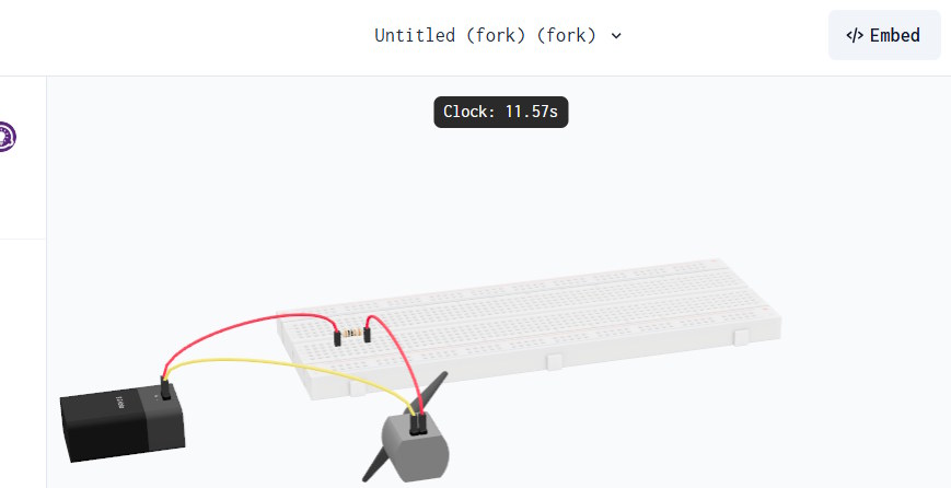
Diode at withdiode.com was a browser-based 3D circuit editor for arranging parts on a virtual breadboard and testing the design with a simulator. At the time this guide was reviewed, the website and its embedded sample were unavailable. The original workflow is preserved below for returning users, followed by criteria for choosing a working alternative.
Availability note: Do not create an account or enter personal information on a look-alike domain. Verify that the official withdiode.com address is operating before following these steps.
How the Diode workflow was organized
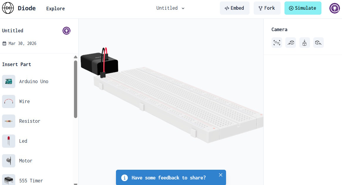
The editor combined a component library, a 3D work area, wire controls, camera/view tools, and a Simulate command. A saved project could be reopened from the user's account. This made the tool useful for demonstrating physical placement as well as basic circuit behavior.
1. Create a project
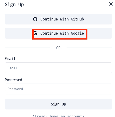
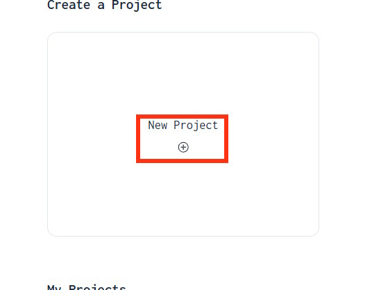
After signing in on the official site, select New Project. Start with a small circuit whose expected behavior you understand—for example, a power source, current-limiting resistor, LED, and return connection.
2. Learn the editor before wiring
In the original interface, components appeared on the left and viewing controls appeared on the right. Rotate or zoom the model so that breadboard rows, power rails, and component pins are visible. Before connecting anything, identify which holes are electrically joined inside the virtual board.
3. Add components and make connections
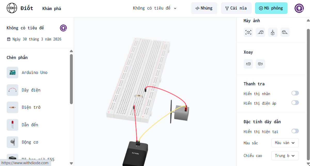
Drag the required parts into the work area. Connect the power path one section at a time and use wire colors consistently—for example, one color for supply and another for return. Clicking a wire exposed appearance and connection controls in the original editor.
4. Inspect the circuit before simulation
- Trace a complete path from the supply through the load and back to the return.
- Check component polarity, especially LEDs, diodes, electrolytic capacitors, and integrated circuits.
- Confirm that a resistor or other current-limiting element has the intended value.
- Look for accidental shorts between the supply and return rails.
- Compare the breadboard layout with a schematic rather than relying only on its appearance.
5. Run the simulation and diagnose the result
Select Simulate. If the circuit does not behave as expected, stop the simulation and inspect one section at a time. Check the virtual supply, ground, component orientation, breadboard row, and wire endpoints. Changing several parts at once makes the original fault harder to find.
If Diode remains unavailable
Choose a simulator according to the task rather than by visual style alone. A suitable classroom replacement should clearly state which components and microcontrollers it models, whether projects can be shared, what account data it collects, and whether it runs on student devices.
- For physical breadboard practice: look for a 3D layout and pin-level wiring.
- For circuit theory: prioritize a schematic view, measurements, and visible voltage or current behavior.
- For microcontroller lessons: confirm support for the exact board and programming language.
- For engineering analysis: use a documented SPICE-capable tool and appropriate manufacturer models.
- For schools: review age requirements, sign-in options, privacy terms, sharing permissions, and export formats.
Simulation is not a safety guarantee
A simulator simplifies real components and cannot reproduce every tolerance, wiring fault, heat condition, or failure mode. Treat a successful run as a learning and debugging aid—not proof that a physical circuit is safe. In classrooms, use teacher-approved low-voltage supplies and components, disconnect power before rewiring, and obtain qualified supervision for any project involving mains electricity, batteries capable of high current, or unfamiliar hardware.
The original non-YouTube Diode iframe was removed because the service was unavailable and embedded third-party frames are not retained in this revision.
Related Articles
 How to Create Visual Vector Simulations3 minutes read
 Create Interactive Simulations of Mathematical Concepts on ChatGPT5 minutes read
 5 Creative Ideas for Old Circuit Boards6 minutes read
 Top 5 Best Circuit Drawing Software 20215 minutes read
 Why Is the Apple Printed Circuit Board Black While Most Other4 minutes read
 Top Best Electronic Circuit Design Software4 minutes read
Reader Comments 0
Sign in with email or Google to join the discussion.