Table of Contents
To make a standard Ethernet patch cable, terminate both ends with the same wiring scheme—T568A or T568B—and verify all eight conductors with a cable tester. T568B is common in many installations, but consistency with the existing site standard matters more than choosing A or B.
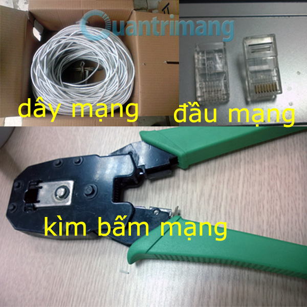
Tools and materials
- Solid- or stranded-conductor twisted-pair cable of the required category
- 8P8C modular plugs, commonly called RJ45 plugs, specifically rated for that cable’s category, conductor type, and diameter
- A compatible stripping and crimping tool
- An Ethernet cable tester
- Optional strain-relief boots
Do not use an RJ11 telephone plug. For permanent in-wall cabling, standards-based keystone jacks and patch panels are generally preferable to male plugs. Match shielded components and grounding practices when working with shielded cable.
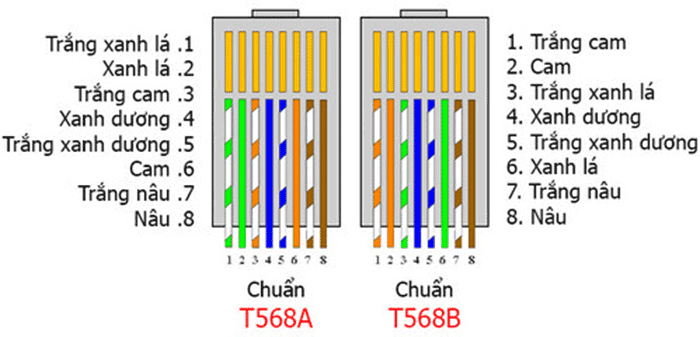
T568A and T568B pin order
Hold the plug with the gold contacts facing you and the locking tab away from you; pin 1 is on the left. Confirm orientation against the plug manufacturer’s diagram because pass-through and load-bar plugs can differ in assembly.
| Pin | T568A | T568B |
|---|---|---|
| 1 | White/green | White/orange |
| 2 | Green | Orange |
| 3 | White/orange | White/green |
| 4 | Blue | Blue |
| 5 | White/blue | White/blue |
| 6 | Orange | Green |
| 7 | White/brown | White/brown |
| 8 | Brown | Brown |
A straight-through cable uses the same scheme at both ends. A crossover cable uses T568A at one end and T568B at the other. Most modern Ethernet ports support auto-MDI/MDIX, so a straight-through cable normally works even between similar devices. Make a crossover cable only for legacy equipment that specifically requires it.
How to crimp the cable
1. Cut and strip the jacket
Cut the cable square. Strip only enough outer jacket to arrange the conductors and seat them in the plug—usually about 25 to 30 mm, depending on the connector. Do not nick the conductor insulation.
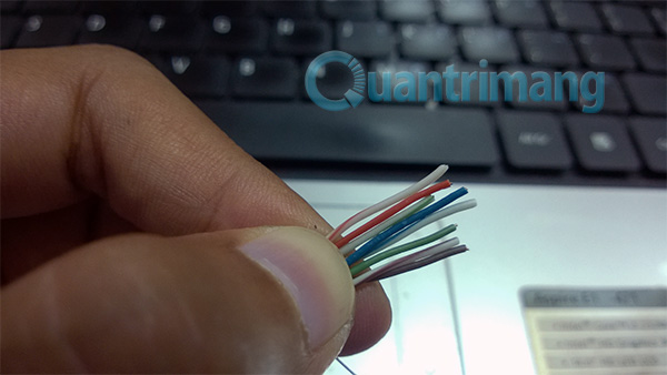
2. Arrange and trim the conductors
Untwist each pair only as much as necessary. Arrange the wires in the selected T568A or T568B order, flatten them between your fingers, then trim all eight ends evenly. Excessive untwisting increases crosstalk and can make a cable pass continuity but perform poorly at higher speeds.
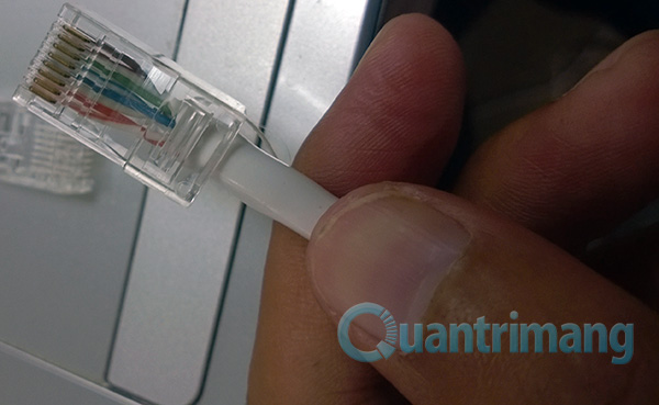
3. Insert the wires fully
Push the conductors into the plug until every wire reaches the front. Check the color order through the transparent body. The cable jacket—not just the individual wires—should extend under the plug’s strain-relief tab.
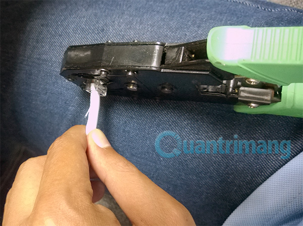
4. Crimp the plug
Place the plug completely into the matching crimp die and squeeze the tool through its full cycle. Inspect the contacts and strain relief, then terminate the other end using the intended scheme.
Test before using the cable
Connect both ends to a cable tester. For a straight-through cable, pins 1 through 8 should map to the same numbers at the far end. A basic tester can find opens, shorts, reversals, and many miswires. Be alert for a split pair: the pin numbers may look continuous while conductors from different twisted pairs were mixed, causing interference and poor link performance.
A link light is not a complete test. After the wire map passes, connect the cable and confirm the expected negotiated speed and stable data transfer. If Windows reports a disconnected cable, follow the network-cable troubleshooting guide. For a larger installation, see how to set up a wired Ethernet network.
Should you crimp without a proper tool?
Using a screwdriver to press the contacts can leave uneven terminations, damage the plug, or create an intermittent connection. It also may not secure the cable jacket. If the cable matters, use the correct crimping tool or install a tool-less field-termination plug that is explicitly designed for that purpose. Replace any improvised termination as soon as possible.
Common mistakes
- Using plugs that do not match solid versus stranded cable
- Viewing the plug from the wrong side and reversing the pin order
- Using A at one end and B at the other unintentionally
- Leaving too much untwisted conductor outside the jacket
- Failing to seat all wires against the nose of the plug
- Testing only for a link light instead of checking the wire map
For a technical comparison of the two recognized pinouts, see Fluke Networks’ T568A and T568B reference.
Related Articles
 Ethernet Copper Cable: Distinguish Common Network Cables23 minutes read
 Ethernet Cable and How It Works6 minutes read
 Wi-Fi Network Security: How to Use and Security of Wi-Fi Network21 minutes read
 The 5 Top Cat 8 Ethernet Cables of 2024: Recommended Choices6 minutes read
 Wires: How to Crimp Rj459 minutes read
 How to Check the Safety Cable for Your iPhone3 minutes read
Reader Comments 0
Sign in with email or Google to join the discussion.