How to Build a Robot at Home
Do you want to learn how to build your own robot? There are a lot different types of robots that you can make by yourself. Most of the people want to see a robot perform the simple tasks of moving from point A to point B. You can make a....
Part 1 of 6:
Assembling the Robot
-
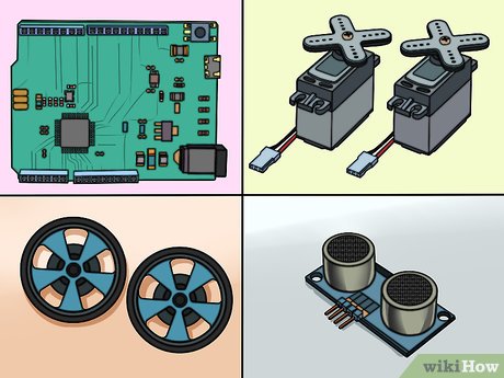 Gather your components. In order to build a basic robot, you'll need several simple components. You can find most, if not all, of these components at your local electronics hobby shop, or at a number of online retailers. Some basic kits may include all of these components as well. This robot does not require any soldering:
- Arduino Uno (or other microcontroller)[1]
- 2 continuous rotation servos
- 2 wheels that fit the servos
- 1 caster roller
- 1 small solderless breadboard (look for a breadboard that has two positive and negative lines on each side)
- 1 distance sensor (with four-pin connector cable)
- 1 mini push button switch
- 1 10kΩ resistor
- 1 USB A to B cable
- 1 set of breakaway headers
- 1 6 x AA battery holder with 9V DC power jack
- 1 pack of jumper wires or 22-gauge hook-up wire
- Strong double-sided tape or hot glue
-
 Flip the battery pack over so that the flat back is facing up. You'll be building the robot's body using the battery pack as a base.
 -
 Align the two servos on the end of the battery pack. This should be the end that the battery pack's wire is coming out of The servos should be touching bottoms, and the rotating mechanisms of each should be facing out the sides of the battery pack. It's important that the servos are properly aligned so that the wheels go straight. The wires for the servos should be coming off the back of the battery pack.
 -
 Affix the servos with your tape or glue.[2] Make sure that they are solidly attached to the battery pack. The backs of the servos should be aligned flush with the back of the battery pack.
- The servos should now be taking up the back half of the battery pack.
-
 Affix the breadboard perpendicularly on the open space on the battery pack. It should hang over the front of the battery pack just a little bit, and will extend beyond each side. Make sure that it is securely fastened before proceeding. The "A" row should be closest to the servos.
 -
 Attach the Arduino microcontroller to the tops of the servos. If you attached the servos properly, there should be a flat space made by them touching. Stick the Arduino board onto this flat space so that the Arduino's USB and Power connectors are facing the back (away from the breadboard). The front of the Arduino should be just barely overlapping the breadboard.
 -
 Put the wheels on the servos. Firmly press the wheels onto the rotating mechanism of the servo. This may require a significant amount of force, as the wheels are designed to fit as tightly as possible for the best traction.
 -
 Attach the caster to the bottom of the breadboard. If you flip the chassis over, you should see a bit of breadboard extending past the battery pack. Attach the caster to this extended piece, using risers if necessary. The caster acts as the front wheel, allowing the robot to easily turn in any direction.[3]
- If you bought a kit, the caster may have come with a few risers that you can use to ensure the caster reaches the ground. i
Part 2 of 6:
Wiring the Robot
-
 Break off two 3-pin headers. You'll be using these to connect the servos to the breadboard. Push the pins down through the header so that the pins come out in an equal distance on both sides.
 -
 Insert the two headers into pins 1-3 and 6-8 on row E of the breadboard. Make sure that they are firmly inserted.[4]
 -
 Connect the servo cables to the headers, with the black cable on the left side (pins 1 and 6). This will connect the servos to the breadboard. Make sure the left servo is connected to the left header, and the right servo to the right header.
 -
 Connect red jumper wires from pins C2 and C7 to red (positive) rail pins. Make sure you use the red rail on the back of the breadboard (closer to the rest of the chassis).
 -
 Connect black jumper wires from pins B1 and B6 to blue (ground) rail pins. Make sure that you use the blue rail on the back of the breadboard. Do not plug them into the red rail pins.
 -
 Connect white jumper wires from pins 12 and 13 on the Arduino to A3 and A8. This will allow the Arduino to control the servos and turn the wheels.
 -
 Attach the sensor to the front of the breadboard. It does not get plugged into the outer power rails on the breadboard, but instead into the first row of lettered pins (J). Make sure you place it in the exact center, with an equal number of pins available on each side.
 -
 Connect a black jumper wire from pin I14 to the first available blue rail pin on the left of the sensor. This will ground the sensor.
 -
 Connect a red jumper wire from pin I17 to the first available red rail pin to the right of the sensor. This will power the sensor.
 -
 Connect white jumper wires from pin I15 to pin 9 on the Arduino, and from I16 to pin 8. This will feed information from the sensor to the microcontroller.
Part 3 of 6:
Wiring the Power
-
 Flip the robot on its side so that you can see the batteries in the pack. Orient it so that the battery pack cable is coming out to the left at the bottom.
 -
 Connect a red wire to the second spring from the left on the bottom. Make absolutely sure that the battery pack is oriented correctly.
 -
 Connect a black wire to the last spring on the bottom-right. These two cables will help provide the correct voltage to the Arduino.[5]
 -
 Connect the red and black wires to the far-right red and blue pins on back of the breadboard. The black cable should be plugged into the blue rail pin at pin 30. The red cable should be plugged into the red rail pin at pin 30.
 -
 Connect a black wire from the GND pin on the Arduino to the back blue rail. Connect it at pin 28 on the blue rail.
 -
 Connect a black wire from the back blue rail to the front blue rail at pin 29 for each. Do not connect the red rails, as you will likely damage the Arduino.
 -
 Connect a red wire from the front red rail at pin 30 to the 5V pin on the Arduino. This will provide the power to the Arduino.
 -
 Insert the push button switch in the gap between rows on pins 24-26. This switch will allow you to turn off the robot without having to unplug the power.
 -
 Connect a red wire from H24 to the red rail in the next available pin to the right of the sensor. This will power the button.
 -
 Use the resistor to connect H26 to the blue rail. Connect it to the pin directly next to the black wire that you connected a few steps ago.
 -
 Connect a white wire from G26 to pin 2 on the Arduino. This will allow the Arduino to register the push button.
Part 4 of 6:
Installing the Arduino Software
-
 Download and extract the Arduino IDE. This is the Arduino development environment, and allows you to program instructions that you can then upload to your Arduino microcontroller. You can download it for free from arduino.cc/en/main/software. Unzip the downloaded file by double-clicking it and move the folder inside to an easy to access location. You won't be actually installing the program. Instead, you'll just run it from the extracted folder by double-clicking arduino.exe.[6]
 -
 Connect the battery pack to the Arduino. Plug the battery back jack into the connector on the Arduino to give it power.
 -
 Plug the Arduino into your computer via USB. Windows will likely not recognize the device.
 -
 Press .⊞ Win+R and type devmgmt.msc. This will launch the Device Manager.
 -
 Right-click on the "Unknown device" in the "Other devices" section and select "Update Driver Software." If you don't see this option, click "Properties" instead, select the "Driver" tab, and then click "Update Driver."
 -
 Select "Browse my computer for driver software." This will allow you to select the driver that came with the Arduino IDE.
 -
 Click "Browse" then navigate to the folder that you extracted earlier. You'll find a "drivers" folder inside.
 -
 Select the "drivers" folder and click "OK." Confirm that you want to proceed if you're warned about unknown software.
Part 5 of 6:
Programming the Robot
-
 Start the Arduino IDE by double-clicking the arduino.exe file in the IDE folder. You'll be greeted with a blank project.
 -
 Paste the following code to make your robot go straight. The code below will make your Arduino continuously move forward.
#include // this adds the "Servo" library to the program // the following creates two servo objects Servo leftMotor; Servo rightMotor; void setup() { leftMotor.attach(12); // if you accidentally switched up the pin numbers for your servos, you can swap the numbers here rightMotor.attach(13); } void loop() { leftMotor.write(180); // with continuous rotation, 180 tells the servo to move at full speed "forward." rightMotor.write(0); // if both of these are at 180, the robot will go in a circle because the servos are flipped. "0" tells it to move full speed "backwards." }
-
 Build and upload the program. Click the right arrow button in the upper-left corner to build and upload the program to the connected Arduino.
- You may want to lift the robot off of the surface, as it will just continue to move forward once the program is uploaded.
-
 Add the kill switch functionality. Add the following code to the "void loop()" section of your code to enable the kill switch, above the "write()" functions.
if(digitalRead(2) == HIGH) // this registers when the button is pressed on pin 2 of the Arduino { while(1) { leftMotor.write(90); // "90" is neutral position for the servos, which tells them to stop turning rightMotor.write(90); } }
-
 Upload and test your code. With the kill switch code added, you can upload and test the robot. It should continue to drive forward until you press the switch, at which point it will stop moving. The full code should look like this:
#include // the following creates two servo objects Servo leftMotor; Servo rightMotor; void setup() { leftMotor.attach(12); rightMotor.attach(13); } void loop() { if(digitalRead(2) == HIGH) { while(1) { leftMotor.write(90); rightMotor.write(90); } } leftMotor.write(180); rightMotor.write(0); }
Part 6 of 6:
Example
- Follow an example. The following code will use the sensor attached to the robot to make it turn to the left whenever it encounters an obstacle. See the comments in the code for details about what each part does. The code below is the entire program.
#include Servo leftMotor; Servo rightMotor; const int serialPeriod = 250; // this limits output to the console to once every 1/4 second unsigned long timeSerialDelay = 0; const int loopPeriod = 20; // this sets how often the sensor takes a reading to 20ms, which is a frequency of 50Hz unsigned long timeLoopDelay = 0; // this assigns the TRIG and ECHO functions to the pins on the Arduino. Make adjustments to the numbers here if you connected differently const int ultrasonic2TrigPin = 8; const int ultrasonic2EchoPin = 9; int ultrasonic2Distance; int ultrasonic2Duration; // this defines the two possible states for the robot: driving forward or turning left #define DRIVE_FORWARD 0 #define TURN_LEFT 1 int state = DRIVE_FORWARD; // 0 = drive forward (DEFAULT), 1 = turn left void setup() { Serial.begin(9600); // these sensor pin configurations pinMode(ultrasonic2TrigPin, OUTPUT); pinMode(ultrasonic2EchoPin, INPUT); // this assigns the motors to the Arduino pins leftMotor.attach(12); rightMotor.attach(13); } void loop() { if(digitalRead(2) == HIGH) // this detects the kill switch { while(1) { leftMotor.write(90); rightMotor.write(90); } } debugOutput(); // this prints debugging messages to the serial console if(millis() - timeLoopDelay >= loopPeriod) { readUltrasonicSensors(); // this instructs the sensor to read and store the measured distances stateMachine(); timeLoopDelay = millis(); } } void stateMachine() { if(state == DRIVE_FORWARD) // if no obstacles detected { if(ultrasonic2Distance > 6 || ultrasonic2Distance < 0) // if there's nothing in front of the robot. ultrasonicDistance will be negative for some ultrasonics if there is no obstacle { // drive forward rightMotor.write(180); leftMotor.write(0); } else // if there's an object in front of us { state = TURN_LEFT; } } else if(state == TURN_LEFT) // if an obstacle is detected, turn left { unsigned long timeToTurnLeft = 500; // it takes around .5 seconds to turn 90 degrees. You may need to adjust this if your wheels are a different size than the example unsigned long turnStartTime = millis(); // save the time that we started turning while((millis()-turnStartTime) < timeToTurnLeft) // stay in this loop until timeToTurnLeft has elapsed { // turn left, remember that when both are set to "180" it will turn. rightMotor.write(180); leftMotor.write(180); } state = DRIVE_FORWARD; } } void readUltrasonicSensors() { // this is for ultrasonic 2. You may need to change these commands if you use a different sensor. digitalWrite(ultrasonic2TrigPin, HIGH); delayMicroseconds(10); // keeps the trig pin high for at least 10 microseconds digitalWrite(ultrasonic2TrigPin, LOW); ultrasonic2Duration = pulseIn(ultrasonic2EchoPin, HIGH); ultrasonic2Distance = (ultrasonic2Duration/2)/29; } // the following is for debugging errors in the console. void debugOutput() { if((millis() - timeSerialDelay) > serialPeriod) { Serial.print("ultrasonic2Distance: "); Serial.print(ultrasonic2Distance); Serial.print("cm"); Serial.println(); timeSerialDelay = millis(); } }