Adjust bandwidth saving via QoS (Part 2)
In Part 1 of this series, we discussed what QoS is and what it is used for.
 Adjust bandwidth saving via QoS (Part 1)
Brien M. Posey
In Part 1 of this series, we discussed what QoS is and what it is used for. Part 2 of this series will continue by explaining how QoS works. As you read this article, note that the information presented here is based on Windows Server 2003's QoS implementation, which will differ from the original QoS implementation that is included with Windows 2000 Server.
Traffic Control API (Traffic Control API)
One of the biggest problems with prioritizing network traffic is that you cannot prioritize traffic based on computers that have generated it. This is a very common point for a computer running multiple applications, and for each of those applications (including the operating system) to generate its own traffic. When this problem occurs, each traffic stream must be prioritized in different ways. An application may require reserve bandwidth, but the most efficient way of delivery will also be useful for other traffic flows.
This is the reason for introducing the Traffic Control API. The Traffic Control API is a programming application interface that allows QoS parameters to be applied to individual data packets. It works by distinguishing separate traffic streams, then applying different QoS controls for each flow.
The first thing that the Traffic Control API does is to create something known as filtering parameters (filterspec). These criteria are essential for a filter to determine which stream the packet belongs to. Some of the properties used by these filtering criteria include both destination and source IP addresses and port numbers.
Once the filterspec has been defined, the API will allow creation of flow specifications. This flow parameter distinguishes the QoS parameters that will be applied to a sequence of packets. Some of the parameters defined by the flow specifications include the speed of the transmission and the type of service.
The third concept is defined by the Traffic Control API that is thread. The thread is simply a series of packets that must comply with the same flow parameters. For simplicity, filtering parameters will identify which data packets are grouped into flow specifications. The stream specification will show whether the packets are 'processed' for priority and which thread is the actual transmission component of the packets. All packages inside a thread are 'handled' in an equal manner.
One of the advantages of the Traffic Control API compared to the Generic QoS API used in Windows 2000 is the ability to use thread acquisition. If a host has multiple applications that are transferring data streams to a certain destination, these packets can be combined into one stream. This is also done for applications that use different ports, provided the source and destination IP addresses are the same.
Classification of general packages
In the previous section, we introduced the relationship between flow specifications and filtering specifications as well as the flow. One important thing to note is that the Traffic Control API is just an API. It is only the task of recognizing and prioritizing traffic flows that need to be prioritized rather than creating real flows.
Thread creation is the work of the Generic Packet Classifier. You can review the previous section, one of the attributes defined within the flow specification has the service type. Basically, the service type is responsible for defining the priority of the flow. The Generic Packet Classifier is responsible for checking whether the service type has been assigned a thread specification or not, and then injects the relevant packets into a queue to match the service type. Each thread is placed in a separate queue.
Schedule for data packets
The third QoS component you need to know is the packet scheduler (QoS Packet Scheduler). To simplify, you only need to understand the main task of this component is to arrange traffic. Packet scheduler takes data packets from different queues, then marks the priority for packets and thread speeds.
As I explained in Part 1 of this series, for QoS to work properly, different network components are located between the source of the package and its destination must know about QoS. In addition to knowing how to handle QoS they also need to know about how to handle non-priority traffic as well as normal traffic. To do this, QoS uses a marker technique.
There are two types of markup here. QoS Packet Scheduler uses Diffserv markup done in 3rd layer devices and 802.1p made by Layer 2 devices.
Set up QoS package schedule
Before I show you how to mark tasks, you need to set up QoS Packet Scheduler so that it can work. In Windows Server 2003, the QoS Packet Scheduler is treated as an optional network component, similar to Client for Microsoft Networks or TCP / IP Protocol. To enable QoS Packet Scheduler, open the server's network connection properties page, check the QoS Packet Scheduler checkbox as shown in Figure A. If the QoS Packet Scheduler is not in the list, click the Install button and Follow the prompts.
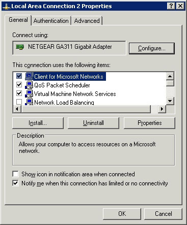
Figure A: QoS Packet Scheduler needs to be enabled before you use QoS
Another thing that you need to know about QoS Packet Scheduler is that, to work properly, your network adapter needs to support how to label 802.1p. To check if support is available, click the Configure button shown in Figure A, Windows will display the properties page for your network adapter. If you look at the Advanced tab, you will see the properties supported by your network adapter.
If you look at Figure B, you will see one of the attributes listed is 802.1Q / 1P VLAN Tagging. It is also possible to see that this attribute is disabled by default. To enable it, just click on the property and click OK.
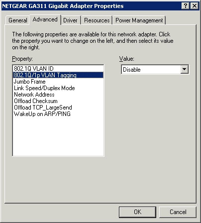
Figure B: You must enable 802.1Q / 1P VLAN Tagging
You can see in Figure B that the property you activated is related to VLAN tagging, not the packet marking. The reason for this is that the priority mark is embedded inside VLAN tags. The 802.1Q standard defines VLANs and VLAN tags. This standard reserves three bits within the VLAN package to be used for priority code retention. However, the 802.1Q standard does not define these priority codes.
The 802.1P standard was created as an improved version for 802.1Q. 802.1P defines the priority markup that can be embedded into VLAN tags. We will show you how these two standards work together in Part 3.
Conclude
In this section, we have introduced you to the basic concepts in the Windows Server 2003 QoS architecture. In Part 3, I will continue the discussion by showing you how to mark QoS packets. Packet Scheduler and discuss both how QoS works in low bandwidth environments.
 Adjust bandwidth saving via QoS (Part 3)
 Adjust bandwidth saving via QoS (Part 4)
- Adjust bandwidth saving via QoS (Part 1)
- Adjust bandwidth saving via QoS (Part 4)
- Adjust bandwidth saving via QoS (Part 3)
- What is Bandwidth?
- How to calculate network bandwidth and transmission required
- Don't waste your Internet traffic, use these 5 bandwidth restriction tools
- How to limit the bandwidth of Windows Update on Windows 10
- 6 ways Windows 10 wastes your Internet bandwidth
- 5 tips to monitor home network bandwidth usage
- Top 10 best bandwidth monitoring software
- Restore deleted components in Active Directory
- Deploy QoS on Windows Server 2012 (Part 1)
- Learn about the concept of QoS on routers
- 5 tips to help make optimal use of Tomato on the Router
- Upgrade the router using Tomato firmware
- Guide to DD-WRT - Part 4: Definition of priorities with QoS
- Adjust bandwidth saving via QoS (Part 3)
- Adjust bandwidth saving via QoS (Part 4)
- Adjust bandwidth saving via QoS (Part 1)
- Instructions for changing settings in Wi-Fi Router
 What is QoS? How to use QoS to get faster Internet speed when you need it urgently
 Deploy QoS on Windows Server 2012 (Part 1)
 Learn about the concept of QoS on routers
 Guide to DD-WRT - Part 4: Definition of priorities with QoS
 Adjust bandwidth saving via QoS (Part 1)