Hardware in OSI reference model: Layer 2

In the previous part of this series, we have introduced the 7-layer OSI reference model and the first layer, which is the physical layer. In the second part of this series, we will introduce the second layer, the data link layer or Data Link, from a hardware perspective.

Hardware in OSI reference model: Layer 2 Picture 1Hardware in OSI reference model: Layer 2 Picture 1 Hardware in OSI reference model: Grade 1

Russell Hitchcock

In the previous part of this series, we have introduced the 7-layer OSI reference model and the first layer, which is the physical layer. In the second part of this series, we will introduce the second layer, the data link layer or Data Link, from a hardware perspective.

Data link layer provides functional and procedural methods for transferring data between two points together. There are five common functions that this class must take responsibility for. These functions are:

  1. Control logical links
  2. Control access to the environment
  3. Frame data
  4. Addressing
  5. Error detected

Control logical links (Logical Link Control - LLC)

Logical Link Control (LLC) is often referred to as a subclass of data link layer (DLL), as opposed to the functionality of DLLs, this LLC subclass is primarily involved in concatenating protocols for submissions. MAC (access control environment). LLC performs this task by dividing the data sent into smaller data frames and adding additional descriptive information about the frame, called frame headers or headers.

Media access control (Media Access Control - MAC)

Like LLC, Media Access Control (MAC) is also considered a subclass of DLL but contrary to the functionality of the DLL, including in this subclass is the MAC address. The MAC address provides this subclass with a unique identifier so that each network access point can communicate with the network. MAC sublayer is also responsible for accessing network cables, or communication environments.

Frame data

If someone sends data to a network. The recipient will have to know how and when to read the data. This problem can occur in a number of ways and is the only purpose of framing. In general terms, framing is the way of organizing data to be transmitted and to identify this data as instructional information, called headers. What and how much information is contained within the headers can be identified by the protocol used on the network, just like Ethernet.

The structure of a frame closely related to the Ethernet protocol is shown in Figure 1 below.

Hardware in OSI reference model: Layer 2 Picture 2Hardware in OSI reference model: Layer 2 Picture 2
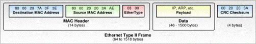
Figure 1: Ethernet frame structure

Addressing

Addressing in layer 2 occurs with the MAC address of the MAC subclass. You should not confuse this with the specified network address or IP address. Combining a MAC address with a network access point and a network or IP address is combined with an entire device (eg computer, printer or router).

Talking about routers, you should note that routers work in layer 3 and not layer 2. Switches and hubs work in layer 2, so sending data is based on layer 2 addressing ( MAC address) and not interested in IP address or network address. However, some routers have some functions of layer 2, with these routers we will introduce it in another article.

Manage and detect errors

Whenever data is sent on the transmission medium, there is a case where the recipient will not receive the data exactly as it was sent. This occurs due to many reasons, such as interference, in some cases the transmission line is too long to weaken the signal. Therefore, it is very important on the receiver side to know if the data has been received with an error. There are several methods to do this. Some of these methods are simple methods but there are many benefits.

Parity bits are an example of a simple error detection protocol, although somewhat limited, but it is widely used. A parity bit is an extra bit added in a data packet. There are two values ​​for each of these bits. This value will depend on how the parity bit is used. There are two ways to detect parity. If even parity is used, even odd bits must be set ('1' or '0') to make the number of '1' in the packet even. Conversely, if using oddness, the parity bit must be set according to the value needed to make the number '1' in the data packet odd.

When using parity bit detection, the receiver will check all '1' bits in the data frame, in which parity bit. The recipient will have a setting for evenness or oddity; If the number of '1' bits in the frame does not match the setting, this means that the data frame is transmitted. However, the effectiveness of this type of error detection method is limited. Its limitation here is that if there is an even number of errors in the same data frame, this method completely loses the ability to detect errors - so a more sophisticated error detection method is needed. .

The method of detecting errors by checking the sum can show us better performance if used with parity bit method. The total test method is to check the sum of all '1' bits in the data packet and check that value for the total value added by the sender for the packet. The general test method may provide some effect for your error detection efforts but it still has some limitations. For example, a checksum cannot detect an even number of errors (since their sum will be zero), some bytes are inserted and their sum is zero, or even reordered. the order of bytes in the data packet. To overcome this situation, there have been several new methods introduced.

One of the most prominent methods of error detection is to check for CRC errors. This method converts a packet into a polynomial, in which the values ​​of the coefficients correspond to the bits in the packet, then divide that polynomial by a predetermined key or a standard key. The rest of the division is sent with the packet to the receiving side. The receiver also performs such polynomial division with the same key as the sender, then checks the received result. If these two results are appropriate, the process of sending the message is successful and there is no error. This method works quite well because there are many possibilities that a polynomial can use a key, but not all polynomials provide the same good error detection. A general principle is that, the longer the polynomial is, the better the ability to detect errors, but the related math problem is quite complex and many technical aspects have some controversy in implementation. So this method provides the best error detection efficiency.

Finally, I want to point out to you that these error detection methods are not limited to data transmission in the network environment; they can be used quite well in data storage scenarios, where people want to check if the data is misleading.

In the next part 3 of this series, I will show you a little more detail about why routers are mostly in layer 3, not layer 2.

Hardware in OSI reference model: Layer 2 Picture 3Hardware in OSI reference model: Layer 2 Picture 3 Hardware in OSI reference model: Layer 2

5 ★ | 1 Vote