Hardware in OSI reference model: Grade 4
In the previous parts of this series, we introduced you to the first three classes in the OSI reference model. In this section, we will introduce you to 4th grade.
Russell Hitchcock
 Hardware in OSI reference model: Grade 1
 Hardware in OSI reference model: Layer 2
 Hardware in OSI reference model: Grade 3
Network Administration - In the previous parts of this series, we introduced you to the first three classes in the OSI reference model. In this section, we will introduce you to layer 4, the transport layer.
Transport layer plays the role of transferring data from one point to another in the network. Responsible for flow control and error recovery. The upper layers in the reference model treat the transport layer as a reliable service, completely independent and seamless from end to end. The 'end-to-end' service within the transport layer is divided into one of 5 different service levels; Transport Protocol (TP) class 0 to TP class 4.
TP class 0
TP class 0 is the most basic level of the 5 classification levels. Services in this class perform segmentation and packaging again.
TP class 1
TP class 1 services perform all the functions of the services classified in TP class 0 in addition to error recovery. This level of service will retransmit data blocks if the recipient does not receive the correct packet.
TP class 2
TP class 2 services perform all the functions of the services classified TP class 1 in addition to channel multiplexing and channel decoding, etc.
TP class 3
TP class 3 services perform all the functions of services TP class 2 in addition to arranging data blocks to send.
TP class 4
TP class 4 services perform all the functions of services TP class 3 in addition to the ability to provide its services on the connection-oriented network or not. This transport protocol layer is the most common and very similar to the Transmission Control Protocol (TCP) set of Internet Protocol (IP).
It is said that TP class 4 is similar to TCP because there are only a few different points. TP class 4 uses 10 data types while TCP only uses 1. This means that TCP is simpler but does not mean that it must contain multiple headers. While TP class 4 is much more complicated, it can include up to a quarter of the headers that TCP contains, so a lot of load is reduced.
Connection-oriented networks
Connection-oriented networks are like your phone networks. A connection is established before data is sent and maintained throughout the entire process of sending data. With this type of network, routing information only needs to be sent while establishing a connection without the need for data transmission. This has greatly reduced the load to improve communication speed. This type of communication is also very useful for applications such as voice and video (the orderly communication type of the receiving data is particularly important).
The networks are not connected
Connectionless networks are completely opposite to connection-oriented networks, they do not send a pre-connection to transmit data. Do not maintain any connection between the two end points. This network requires routing information to be sent in each packet, thus increasing the communication load.
You should note that this problem is because the data being sent in packets does not mean that this is a connectionless network, virtual circuits are an example of a connection-oriented network in the use of data packets such as so.
In the previous sections, I talked about the aspects of error detection and recovery, so in this section we will focus on the hardware and will introduce you to the basic guidelines. in this aspect of the transport layer; Channel multiplexing and decoding.
Multiplexing
Multiplexing is one of the words that people often hear but understand only a few. Many people may know that merging is a process of combining two or more signals into one, but what exactly is it? There are many ways to perform multiplexing. Digital signals can be mixed in one or two ways, time-division multiplexing (TDM) and frequency division multiplexing (FDM). Optical signals use a method that is wavelength-division multiplexing.
To demonstrate how multiplexing works, let's take a simple case in TDM. In this example, we assume that there are two input signals. These two input signals are mixed into one device with 3 inputs; two inputs used for signal and one for clock to control. Two input signals are mixed and output at one output.
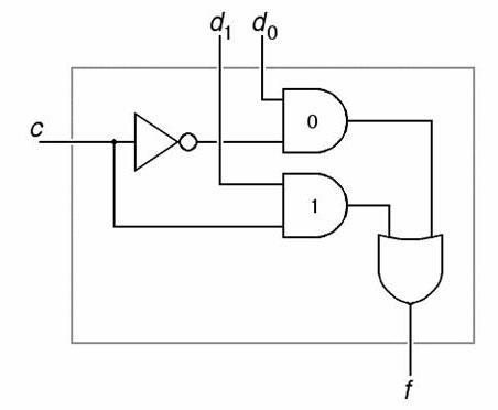
Figure 1: Logic gate diagram of a two-input multiplexer.
Figure 1 above shows a two-input multiplexer. The two signals shown here are d0 and d1, while the control signal is expressed as c. The output of the two input signals is shown as f. The symbols in this figure are standard symbols for representing logic gates. Figure 2 shows the meaning of each of these ports.

Figure 2: Basic logic gates
The multiplexer works by receiving a digital signal on the input c. This c signal goes directly to the input of 1 'AND' port and goes to the 'NOT' port. The 'NOT' gate will reverse the signal, then send it to the input of the 2 'AND' port. The outputs of 'AND' ports will only have a high state when the control signal and the input signal (d0 or d1) are in a high state. Because the control signal is sent through the previous 'NOT' port to a 2 'AND' port, only one of the two 'AND' ports will see a high-status control signal at any instant. This process means that the output f will alternate between signal d0 and d1 with frequency c.
If the frequency of the control signal is more than twice (or more) of the input signal, the output f will have all the information of d0 and d1. And then the decoding side will successfully decode the two input signals d0 and d1. This is the core idea of Nyquist-Shannon sampling theory.
Considering the logic gates in Figures 1 and 2, among those with experience programming and scripting, these logic functions will be recognized as tools in a programmer's popularity. It should be noted that these functions are found in software programs, but here we are completely talking about the hardware functions related to electronic components such as transistors arranged in different ways. Intelligent to implement these logic functions.
Decode the channel
Basic channel decoder is the opposite of a multiplexer. It will have an input signal and in the case described above will need two outputs for two output signals. Obviously, a control signal is also needed and is often referred to as an address signal. This control signal is called an address signal because the channel decoder can also be used to select which output pin to take.
In the next part of this series, we will introduce you to layer 5 in this reference model, please read it.
Was this article helpful?
Your feedback helps us improve.
Related Articles
 Hardware in OSI reference model: Grade 78 minutes read
 Hardware in OSI reference model: Grade 57 minutes read
 Hardware in OSI reference model: Grade 69 minutes read
 Hardware in OSI reference model: Grade 19 minutes read
 Hardware in OSI reference model: Grade 38 minutes read
 Hardware in OSI reference model: Layer 29 minutes read
Reader Comments 0
Sign in with email or Google to join the discussion.