Things to know about Serial ATA (SATA)
Serial ATA (Serial Advanced Technology Attachment) or SATA is a standard hard drive created to replace the parallel ATA interface still known as the IDE. SATA has a transfer rate of about 150MB / s or 300 MB / s compared to a maximum speed of 133 MB / s in previous technologies. This article will show you everything you need to know about Serial ATA.
Serial ATA (Serial Advanced Technology Attachment) or SATA is a standard hard drive created to replace the parallel ATA interface still known as the IDE. SATA has a transfer rate of about 150MB / s or 300 MB / s compared to a maximum speed of 133 MB / s in previous technologies. This article will show you everything you need to know about Serial ATA.
The usual IDE port (now called parallel ATA or PATA) implements parallel data transfer. The advantage of parallel transmission compared to serial transmission in previous mode is high speed, at the same time you can send many bits of data. However, its main weakness is noise noise. Since there are many same wires used (at least one for each bit sent), this wire will cause interference to another wire. This is why ATA-66 and higher hard drives require a special cable of up to 80 wires. The difference between a normal 80-wire cable and a 40-wire cable is that the 80-wire cable has ground wires between the signaling wires, the purpose of the ground wire between the signaling wires is to reduce the interference between them. The current data transfer rate for the parallel IDE standard is 133 MB / s (ATA / 133).
Serial ATA is another technology that allows transmission in serial mode. In the past, we used to think that serial transmission always gave lower speed than parallel transmission. However, this problem is only true if we use the same clock rate. In this case, parallel transmission will have a minimum speed of up to 8 times faster, since it can transmit at least 8 bits (one byte) in a cycle, while only one bit is transmitted. on a cycle with parallel transmission. However, if using a higher clock rate during transmission, it may be faster than parallel transmission. That's exactly what Serial ATA has done.
The problem with increasing the parallel transfer rate is the increase in clock speed, when the higher the clock speed, the more problems arise such as magnetic field interference. Because serial transmission uses only one wire to transmit data, it will reduce the noise noise problem, so it can allow it to use a very high clock rate.
Serial ATA standard transfer rate is 1,500 Mbps. Since it uses 8B / 10B coding - each group of 8 bits is encoded into a 10-bit number - so its effective clock rate is 150 MB / s. Serial ATA devices running at this standard speed are called SATA-150. Serial ATA II provides a number of new features such as Native Command Queuing (NCQ), plus a transfer rate higher than 300 MB / s. Devices that can operate at this speed are called SATA-300. The published standard will be SATA-600.
Keep in mind that SATA II and SATA-300 are not completely synonymous. A standard can build a device that only runs at 150 MB / s but uses new features provided by SATA II, such as NCQ. This device will be SATA II, although it does not work at 300 MB / s.
Native Command Queuing (NCQ) enables increased hard disk performance by reordering commands sent by the computer. If your motherboard has SATA II ports that support NCQ, you should buy a hard drive that supports NCQ.
You should also note that Serial ATA has two separate data paths, one for data transfer and one for data reception. On parallel designs, there is only one data path, which will share both data transmission and reception. Serial ATA cable consists of two pairs of wires (one for transmission and one for receiving) using another transmission method. 3 ground wires are also used so Serial ATA cables have up to 7 wires.
Another advantage in using serial transmission is to use less than the number of wires needed. Parallel IDE ports use 40-pin connectors and 80-wire cables. Meanwhile Serial ATA ports only use 7-pin connector and 7-wire cable. This helps a lot in the radiant aspect of the computer, because using more thin cables will make the air inside the computer's case easier.
In the following figures, you can compare Serial ATA with parallel IDE: how the Serial ATA cable looks and its 80-wire IDE size and the physical aspect comparison of the Serial ATA port. (red in Figure 3) with the parallel IDE port (green in Figure 3).
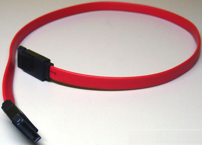
Figure 1: Serial ATA cable
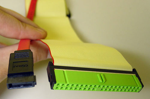
Figure 2: Comparison between Serial ATA cable and 80-wire cable used by parallel IDE devices
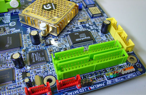
Figure 3: Serial ATA ports (red) and standard parallel IDE ports (green)
Setting
How to install Serial ATA devices is a bit different from standard IDE devices, Serial ATA is a point-to-point connection, meaning that you can only connect one device on one port (the parallel IDE can allow connection Connect two corresponding drives on one port by configuring master / slave). Therefore Serial ATA hard drives can be installed more easily than parallel IDE drives: connect one end of the cable to the Serial ATA port (usually on the motherboard) and the other end of the cable The hard drive you want to connect. Because this connector has a V-shaped engraving, there is no wrong plugging.
Serial ATA standard also has a new 15-pin power connector. This source connection is made standard from the ATX12V specification specification 1.3. So if your computer has an ATX12V 1.3 source or a power source, it will have this connection. Although the 15-pin connection is used, the power connection still uses the 5-pin wires (one +12 V, one +5 V, one +3.3 V and two ground pins).
SATA-300 hard drives have a configuration jumper to work as SATA-150 drives. The problem is that the jumpers installed on the SATA-150 location will limit the performance of the drive if it is installed on a motherboard with SATA-300 ports. The correct configuration for this jumper is very important and we will cover the details of this issue in detail.
Installing SATA hard drives is very simple; remove or change the position of the jumpers SATA-150 / SATA-300 (if available, details will be presented below), connect the Serial ATA cable and the power cable to your shutdown computer.

Figure 4: Connectors of SATA hard drives
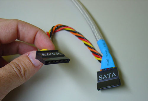
Figure 5: Serial ATA power connectors on ATX12V power supplies
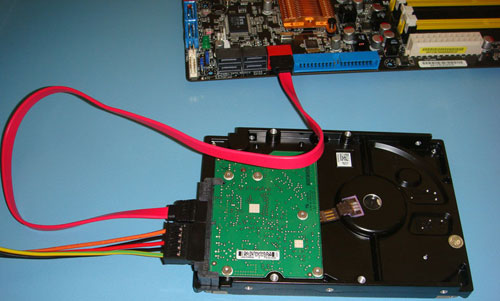
Figure 6: SATA hard drive is connected to the motherboard
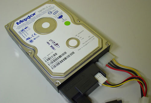
Figure 7: Standard IDE drive ' converted' to Serial ATA via one
adapter Jumper SATA-150 / SATA-300
Some SATA-300 hard drives do not work properly on motherboards containing SATA-150 ports due to the number of SATA-300 hard drives with SATA-150 / SATA-300 jumpers (also known as jumper 1.5 Gbps / 3 Gbps). The problem is that, by default, this jumper is configured in the 'SATA-150' position, limiting your drive performance if installed on the motherboard with SATA-300 ports. We will talk about the impact of performance while configuring the wrong SATA-300 below.
Before installing the SATA-300 hard drive you need to check if it has a SATA-150 / SATA-300 jumper and see if it is configured correctly: if you have an old motherboard with SATA-150 ports, you should leave the jumpers in the SATA-150 position, but if your motherboard supports SATA300, then switch to this position. This information can be found on the drive label, as shown in Figure 8.
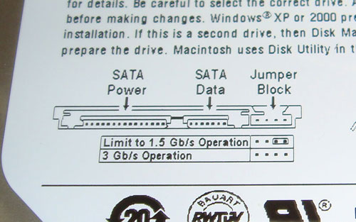
Figure 8: Detailed information on the drive label explains the SATA-150 / SATA-300 jumpers.
This hard drive (Seagate Barracuda 7200.10 160 GB) has a jumper that limits the drive's performance to 150 MB / s (1.5 Gbps), see Figure 9. To make it work properly in SATA-300 drive mode, We need to switch jumpers (see diagram on Figure 8). In this case the jumper can be removed with a small screwdriver. Note that depending on the model of the drive you can switch jumpers instead of removing it. Therefore, you need to consider what is written on the hard drive label.

Figure 9: Hard disk drive with SATA-150 / SATA-300 jumpers being placed in 'SATA-150' position
What affects the performance of the SATA-300 drive when configured incorrectly? We will create some lab tests to introduce you to this issue. We measured the transfer rate of Seagate Barracuda 7200.10 160 GB hard drive with 3 different programs, SpeedDisk32, HD Tach and HD Tune, first of all jumpers on its default configuration ('SATA-150') then remove the jumpers and make the hard drive a true SATA-300 drive. You can see the results in the pictures below
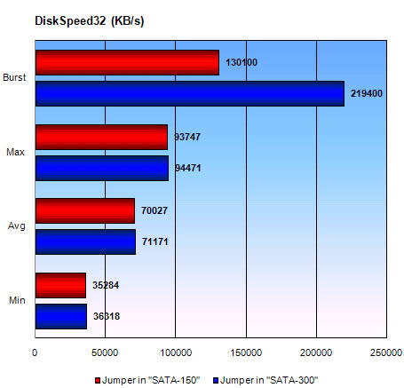
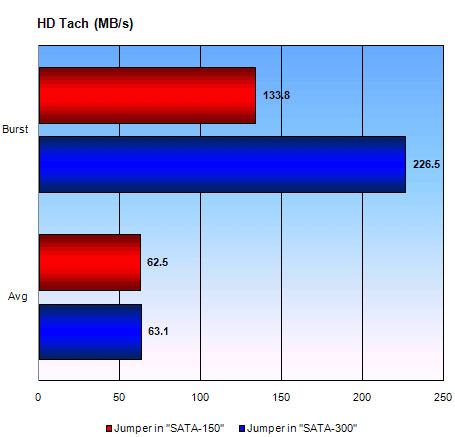

As you can see in the results of the three programs. Although the largest, medium and smallest speeds are the same, with SATA-300 jumpers, burst transmission rates have been increased by about 60% to 69%. In short, you should not forget to check. See if jumpers are positioned correctly when installing SATA-300 hard drives!
Port multiplier
The port multiplier is a device that extends the number of hard drives installed on the same SATA port to 15.
It has a few applications, like allowing home users to install more hard on one SATA port and allow drive rack to use less cable.
With Serial ATA, it is easy to connect the hard drives outside the computer case at the speed of shaving because the cable is used (thinner than the previous 80-wire cable). However, if we need to install a price of up to 16 hard drives into a server, this will be 16 Serial ATA cables from the rack to the server, and the server must have 16 SATA ports. We will demonstrate to you this problem in Figure 10.
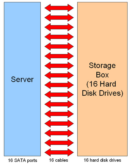
Figure 10: Connecting a server with 16 drives
Using a port multiplier can be connected using less cables. A port multiplier connected to a SATA port will allow you to connect up to 15 drives. And so you only need one cable to connect the rack to the server.
However, in this case, there is a performance issue. If the SATA-150 port is used, the 150 MB / s bandwidth will have to be distributed to all 15 drives, which can cause a bottleneck.
To solve this problem, another method was introduced. Instead of using only one port multiplier chip, you can use 4 to connect the hard drive price to the server with 4 cables (instead of 16). The maximum transfer rate between the server and the price will be 600 MB / s (4x 150 MB / s) if using SATA-150 ports or will be 1,200 MB / s (4x 300 MB / s) if using the SATA-300 port. Inside the rack, you can install up to 60 hard drives (15x4), but to get optimum performance you should install 4 hard drives on each chip, so there will be all 16 drives. We have demonstrated this scenario in Figure 11.
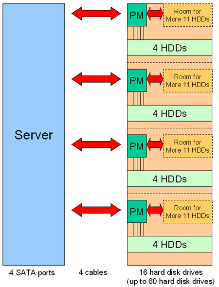
Figure 11: Connecting the server with 16 drives corresponding to the port multiplier
Foot diagram
These are pins for both data cable and Serial ATA power cable. As mentioned earlier, Serial ATA uses two separate data channels, named A and B, using different transmissions, hence the + and - signs below. On strings marked with '-' signs, data is an inverted copy of what is being transmitted on the wires corresponding to the '+' signal.
Serial ATA data connector
Foot
Function
first
Land
2
A +
3
A-
4
Land
5
B-
6
B +
7
Land
Serial ATA power connector
Foot
Function
first
+3.3 V
2
+3.3 V
3
+3.3 V
4
Land
5
Land
6
Land
7
+5 V
8
+5 V
9
+5 V
ten
Land
11
Reserve / Land
twelfth
Land
13
+12 V
14
+12 V
15
+12 V
Was this article helpful?
Your feedback helps us improve.
Related Articles
 Is SAS or SATA the best storage device connection?6 minutes read
 What is serial number?3 minutes read
 Instructions on how to find serial numbers of Windows computers5 minutes read
 Instructions on how to check which SATA HDD slot the hard drive supports?6 minutes read
 4 ways to fix IDM error Fake Serial Number5 minutes read
 Instructions on how to find the serial number of the Mac4 minutes read
Reader Comments 0
Sign in with email or Google to join the discussion.