Hardware in OSI reference model: Grade 1
The Open System Interconnect (OSI) reference model is a model developed by the Open System Interconnect (OSI), which describes how data from an application on a computer is transmitted to an application on a computer. how different. M & o
Russell Hitchcock
The Open System Interconnect (OSI) reference model is a model developed by the Open System Interconnect (OSI), which describes how data from an application on a computer is transmitted to an application on a computer. how different. OSI reference model consists of 7 layers, each layer holds different network functions. Each function of a network can be assigned to one or more adjacent classes, of these 7 classes, and independent of other classes. This independence means that this class does not need to know what the addition of an adjacent class is, merely communicating with it. This is a great advantage of the OSI reference model and is one of the main reasons why it has become one of the most widely used architecture models for communication between computers.
The 7 layers of the OSI reference model are shown in Figure 1 below:
-
Application - application
-
Presentation - performance
-
Session - session
-
Transport - transmission
-
Network - network
-
Data link - data link
-
Physical - physics
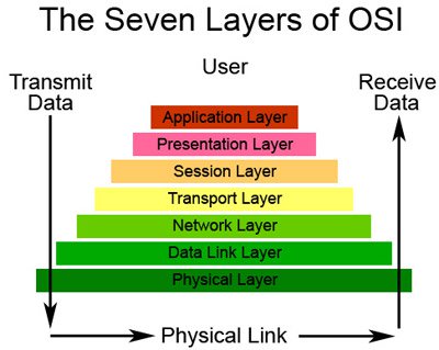
Figure 1: Diagram of classes in the reference model
In the next few articles we will introduce each class in the model and network hardware related to that class. In this article, as you can guess after reading the title, we will introduce to class 1, which is the physical layer.
Many people may assume that all network hardware belongs to the physical layer, they are completely wrong. Many network hardware devices can perform functions belonging to higher layers. For example, the network router that performs routing functions belongs to the network layer.
So what does the physical layer include? The physical layer involves transmitting signals in the environment from one computer to another. This layer contains technical details about electrical and mechanical characteristics such as voltage level, signal timing, data rate, maximum transmission length and physical connections of network equipment. In order for a device to operate only in the physical layer, it will not have any knowledge about the data it transmits. A physical class device simply transmits or receives data.
There are 4 main functions of the physical layer. These functions are:
-
Definition of hardware specifications
-
Encryption and signaling
-
Play and collect data
-
Physical network design and network topology
The definition of hardware specifications
Each piece of hardware in a network will have a lot of technical details. These specifications include components such as the maximum cable length, cable width and electromagnetic interference protection, even flexibility.
Another area of hardware specifications is physical connections. It includes both the shape and size of connections as well as the number of pins and layout if appropriate.
Encryption and signaling
Encryption and signaling are a very important part of the physical layer. This process can be quite complicated. For example, let's see Ethernet. Most people know that the signal is sent as '1' and '0' by using high and low voltage levels corresponding to the above two states. This is indeed beneficial for some teaching purposes, but it is not true at all. Signals on Ethernet are sent using Manchester encoding. This means that '1' and '0' are transmitted as rise and fall in the signal. Please allow us to explain further.
If you send signals on a cable, the high voltage level shows '1' and the low voltage level indicates '0', then the receiver side will also need to know that signal pattern. This is done by a clock signal pulse being transmitted. This method is called Non-return to Zero (NRZ) code, this code has some pretty serious disadvantages. First, if the group of clock signals with the transmitted signal will have two signals. If you do not want to broadcast the clock signal, you can group an internal clock in a receiver but must be in perfect synchronization with the transmitter side clock. Let's assume you can synchronize the clocks (often done very hard because of the very high transfer rates), but there is still a problem keeping it in sync when there is a long interval of the same bits being transmitted; It is the transition to synchronize the clock.
The limitations of NRZ code can be overcome by technology introduced in the 40s at Manchester University, in Manchester, UK. Manchester code combines clock signal with data signal. Not only does it increase the signal bandwidth, it also makes data transmission easier and more reliable.
Manchester encoded signals will transmit data such as up and down angles. The presence angle is '1' and '0' needs to be decided in advance but both need to consider Manchester encoded signals. The Ethernet and IEEE standards use the up angle as the logic '1'. The original Manchester code uses the down angle as the logical level '1'.
One situation where you can think about it is that if you need to transmit two '1' signals in a row, the signal will be at a high voltage and it will be difficult to identify the two signals on the receiver. This is completely resolved because the up and down angles correspond to the data that is transmitted in the middle of the bit boundary; The angle of the bit boundaries consists of the transmitter or not, it places the input signal into the correct position for the next bit to be transmitted. The end result in the middle of each bit is a transition, the direction of the transition will represent '1' or '0' and the time of conversion is equal to the period of the clock.
Although there are many other coding mechanisms that can be more advantageous than NRZ or Manchester, but with simplicity and reliability, the Manchester code still has value and is still widely used.
Play and receive data
Whether the network environment is an electrical cable, fiber optic cable or radio waves, it is necessary to have a device to transmit physical signals. On the contrary, there is also a need to acquire the physical signals. In a wireless network, this transmission and reception is done by antennas that transmit or receive signals with pre-assigned frequencies with a preset frequency band.
Optical transmission lines using equipment can create and receive light pulses, the frequency of this pulse is used to determine the logical value of the bit. Devices such as general image amplifier and repeater are used in long-distance optical transmission, which are also grouped into the physical layer in the OSI reference model.
Topology and physical network design
Network topology and network design are also grouped into the physical layer. Whether your network is token ring, star, mesh, or hybrid topology is still in the physical layer.
Also a grouped component in the physical layer is the available layout cluster.
In general, all you need to remember is that if a piece of hardware does not know the data being transmitted on it, it will be grouped into the physical layer in the OSI 7-layer reference model. In the next part of this series, we will introduce you to the Data link layer, and introduce its differences to other classes and its hardware in this reference model. .
 Hardware in OSI reference model: Layer 2
 Hardware in OSI reference model: Grade 3
Was this article helpful?
Your feedback helps us improve.
Related Articles
 Hardware in OSI reference model: Grade 48 minutes read
 Hardware in OSI reference model: Grade 78 minutes read
 Hardware in OSI reference model: Grade 57 minutes read
 Hardware in OSI reference model: Grade 69 minutes read
 Hardware in OSI reference model: Grade 38 minutes read
 Hardware in OSI reference model: Layer 29 minutes read
Reader Comments 0
Sign in with email or Google to join the discussion.