How to create an Ethernet crossover cable
Ethernet cables have been considered standard in network settings for years. It is the fastest way to connect PCs to a router or hub adapter. Sure, you can use a wireless connection for more convenience, but the fact that wireless connectivity will always be slower, and especially susceptible to interference.
Today's article will describe how to press the Ethernet crossover network. Let's find out soon!
How to create an Ethernet crossover cable
- What is a crossover cable?
- Why can you not need to use crossover cable?
- What do you need to create Ethernet crossover cables?
- How to create a crossover cable
What is a crossover cable?
In an Ethernet network environment - like in a home with many wired computers - all computers must connect to a central router. The router will take all the bits sent from computers and transfer them to other devices on the network, or to an external network. However, a crossover cable can be used to connect two devices directly, without the need for a router in the middle.
It simply reverses some of the pins, so that the output on one computer is sent to the input of another computer. Some people may have memories of using a crossover cable to play multiplayer games, before the Internet became popular.
Connecting two machines is a use of crossover cables. Another advantage is to extend the network by connecting another network adapter, thereby giving you more ports.
Why can you not need to use crossover cable?
After being explained how to use crossover cables, you should know that you may not need to use crossover cables. Most network devices are currently equipped with convertible ports called "autosensing" or "uplink". This is one of two software used to automatically detect when a port will be running in cross mode, or give you a physical switch, which you can use to activate this mode. They make cross-operation pins in the hardware switch itself.
In fact, you really only need a crossover cable if you are dealing with very old hardware (such as a hub), or if you want to quickly connect two computers in a network-free environment.
Even then, nearly all modern hardware will automatically detect what you are trying to do, and configure the Ethernet port appropriately without a crossover cable.
What do you need to create Ethernet crossover cables?
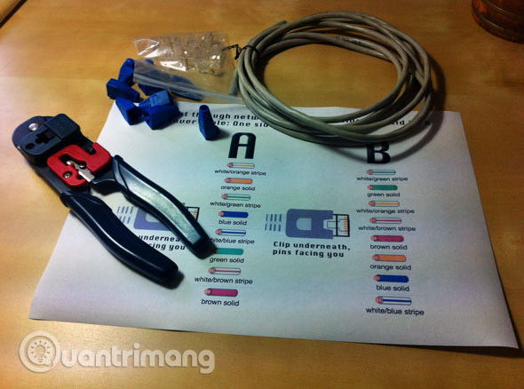
- An Ethernet cable (Sure enough): The article will use CAT5. Seriously, CAT5 is certified with true gigabit support, but in fact, older CAT5 cables are better used in short distances.
- A crimping tool: This 'all-in-one' tool is specially shaped to push the pins into the plug and can remove the protection cables, as well as cutting.
- 2 RJ45 plugs.
- 2 shield plugs (Optional).
The crossover cable is just a normal network cable but connects the transmitter pair of this computer to the receiving pair of the other computer and vice versa, so it can allow two computers to communicate with each other.
So what's different about this cable is not about the material, the wire or the connector, it's just an ordinary twisted cable with the inner wires of the connected connector slightly different on the other end. . You can buy this cable that has been prefixed or made by yourself if you have good manipulation skills.
In Figure 1, you can see how a crossover cable is. The cable itself is just a normal twisted-pair network cable. The color here doesn't matter.
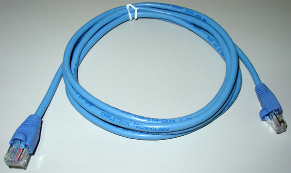
Figure 1: Crossover cable
The trick lies in one of the connectors. If you compare both connectors, you will see that the order of the pairs at the top is completely different from the order of the other end (each wire has its own color). On a pin-to-battery cable, both connectors use the same wire order.
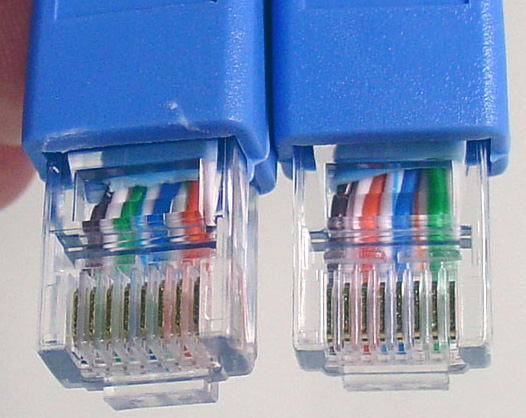
Figure 2: The order of the different wires, that instruction is the crossover cable
(You can compare the position of the strings that orange and blue)
In addition to the above tools, you will also need a diagram to click the network, it is best to print out for easy monitoring. Note that parts A and B are not simply reversing each other:
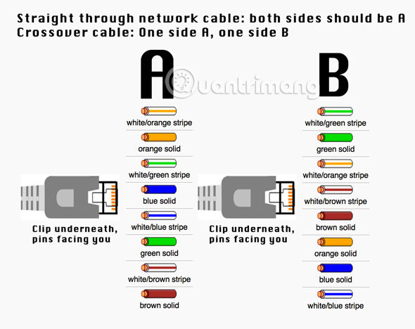
To help you make a cable yourself, we will introduce the order of the wires in the table below.
First order A Wire color First order B 1 White with green stripe 3 2 Green 6 3 White with orange stripe 1 4 Blue 4 5 White with blue stripe 5 6 Cam 2 7 White with 7 8 Brown stripes 8The table above is for 100Mbps networks. If you want to design a Gigabit Ethernet (1000BaseT) crossover cable, you need to follow the order shown in the table below (you also need to use Cat5e cable). This is because Gigabit Ethernet uses two pairs to transmit data and two pairs receive data.
First order A Wire color First order B 1 White with green stripe 3 2 Green 6 3 White with orange stripe 1 4 Blue 7 5 White with blue stripe 8 6 Cam 2 7 White with brown stripe 4 8 Brown 5How to create a detailed crossover cable
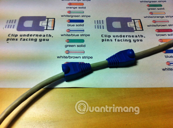
Start by screwing some shields into the cable. It will be easier to do this now.
Cut off the cable cover at both ends, each end about 1.5cm with the tool mentioned above.
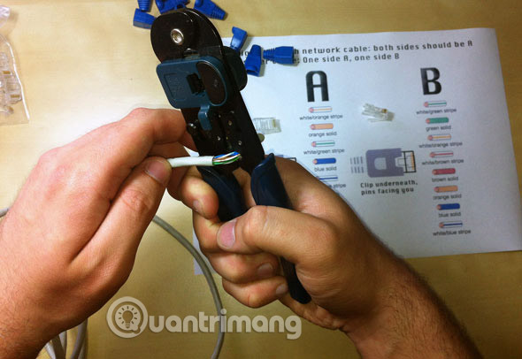
Remove the wires (note that there must be 4 "twisted pairs"). Arrange them in the order shown on the diagram, from top to bottom, one end to A, one end to B.
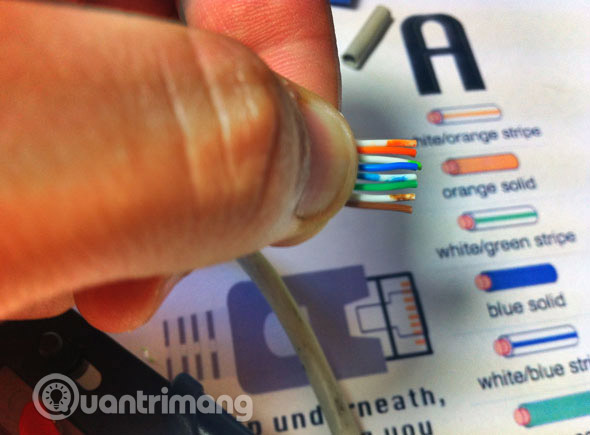
Once you have correctly identified the strings as in the diagram, group them together in a row. If the strings are short and irregular, fix it a bit so that they are of equal length.
The hardest part is putting them on the RJ45 plug without disturbing the order. Hold the plug with the clamp face facing out; The gold pins must be facing towards you, as shown below.
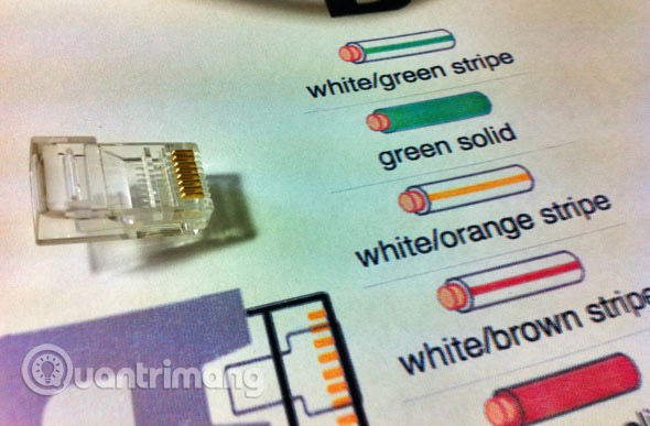
Push the cable in the right direction. The cable should be just as long as the slot at the end of the plug. Cut back the cables if necessary.
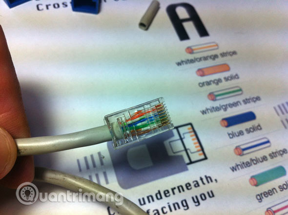
When the cables are firmly attached to the plug, plug it into the crimping tool and press down.
Do the same with the other end, using the B diagram instead.
If you do not have a cable test device, the easiest way to check is to plug in the device. Try connecting two computers directly to each other. The status LED changes with the device, but normally an LED will show up, while the other indicator indicates the speed.
Good luck!
See more:
- Build a network crossover cable
- Press cross cable for 1 Gigabit network card - EASY or DIFFICULT?
- Comprehensive guide for home networking