Table of Contents
An Ethernet hub repeats incoming signals to every other port. A switch learns which devices are reachable through its ports and normally forwards a known unicast frame only toward its destination. That difference makes a switch the practical choice for connecting wired devices in a modern home or office network.
This comparison concerns Ethernet network hubs, not USB hubs or smart-home hubs.
How an Ethernet hub works
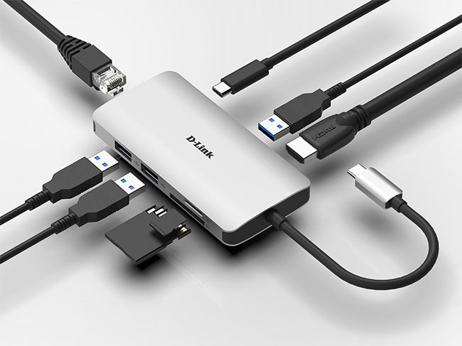
A hub is a multiport repeater operating at the physical layer, Layer 1 of the OSI model. It regenerates an incoming electrical signal and sends it out through the other ports. It does not read destination MAC addresses or maintain a forwarding table.
Devices on a hub share bandwidth and one collision domain. Traditional hub-based Ethernet uses half-duplex communication: devices cannot transmit and receive simultaneously on the shared segment. When transmissions collide, Ethernet's collision-handling mechanism makes the devices retry.
Calling a powered Ethernet repeater hub “passive” is misleading. Repeating a signal requires active electronics; the important limitation is its lack of frame-level forwarding decisions.
How a switch works
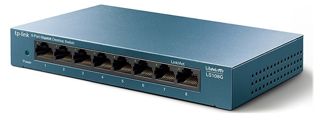
A Layer 2 switch handles Ethernet frames. It records a frame's source MAC address and the port where the frame arrived, then looks up the destination MAC address to decide where to forward it. This information is stored in a MAC address table, often called a CAM table.
A switch does not send every frame exclusively to one port. Broadcast frames and unknown unicast frames are normally flooded to eligible ports in the same VLAN, excluding the incoming port. Multicast handling depends on the switch's configuration and features. Cisco's MAC forwarding documentation explains these distinctions.
On a correctly negotiated full-duplex link, a device and switch can send and receive at the same time without Ethernet collisions. Separate port links also allow several device pairs to communicate concurrently, subject to the switch's capacity and any shared uplink.
Hub and switch comparison
| Feature | Ethernet hub | Ethernet switch |
|---|---|---|
| OSI layer | Layer 1 | Layer 2 for ordinary switching; some models also provide Layer 3 routing |
| Forwarding decision | Repeats the signal to other ports | Uses destination MAC addresses and learned port mappings |
| MAC address learning | None | Learns source MAC addresses |
| Bandwidth and collisions | Shared segment and collision domain | Separate port links; no collisions on full-duplex links |
| Duplex | Half-duplex | Normally full-duplex; legacy support varies |
| Port speeds | Legacy equipment commonly used 10 or 100 Mbps | Model-dependent; gigabit, multi-gigabit, and faster ports are available |
| Configuration features | No VLAN or frame-filtering controls | Managed models may offer VLANs, monitoring, QoS, and access controls |
| Internet requirement | Can connect a local network without internet access | Can connect a local network without internet access |
A switch does not replace the router that connects different networks or provides internet access. See the differences between switches, routers, and modems if you are planning how the devices fit together.
Choosing a switch for your network
Management features
| Type | Typical controls | When it is useful |
|---|---|---|
| Unmanaged | Basic forwarding, with little or no configuration | A simple network that needs more wired ports |
| Smart or easy-managed | Selected controls, often including VLANs and QoS | A small network needing basic traffic separation |
| Managed Layer 2 | More detailed VLAN, monitoring, security, and traffic controls | An office or other network requiring administration |
| Layer 3 | Switching plus supported routing features | A design that needs routing between VLANs |
Marketing categories vary. A managed switch does not automatically include PoE, stacking, cloud management, or dynamic routing; confirm those features in the exact model's specifications.
Ports, speed, and uplinks
Count devices and leave room for expansion, remembering that a connection to the router or another switch also uses a port. Choose port speeds that match the devices, cabling, and intended workload. A fast switch cannot make an older network adapter faster.
Check the uplink separately. Several devices transferring large files to a server through one link may contend for that link's capacity. Choose the uplink using expected simultaneous traffic, rather than assuming every access port always runs at its maximum speed. For a basic wiring example, see how to set up a local area network.
Power over Ethernet
PoE can power compatible access points, cameras, and IP phones through the Ethernet cable. Match the device's required PoE standard and power class, then check both the per-port limit and the switch's total power budget.
Common switch-side limits are 15.4 W for 802.3af, 30 W for 802.3at, and up to 60 or 90 W for the relevant 802.3bt type. Less power is available at the device after cable losses. A switch with enough PoE ports can still lack the total budget to power them all as required.
Replacing an old hub
For an ordinary network, a compatible switch can often replace a hub while retaining the existing devices, cabling, and IP configuration. Check negotiated speed and duplex afterward, especially on old equipment with manually configured interfaces.
If a monitoring tool relied on seeing all hub traffic, an ordinary switch port will no longer provide that view. Use an appropriate network tap or a managed switch's port-mirroring feature for authorized capture. Port mirroring has its own capacity limits, so it is not automatically a lossless recording of every packet.
Related Articles
 Distinguish Between Switches, Routers and Modems7 minutes read
 Difference Between IF and Switch Functions in Excel7 minutes read
 What Is the Difference Between Cherry MX and Topre? Complete Guide10 minutes read
 Switch in C: What to Know5 minutes read
 Blue Switch Mechanical Keyboards: Features and Comparisons9 minutes read
 What Is the Difference Between Hex, Rgb and Hsl?5 minutes read
Reader Comments 0
Sign in with email or Google to join the discussion.