How to Measure Speaker Impedance
A speaker's impedance is a measure of a device's ability to resist alternating current. Impedance is inversely proportional to the current that the speaker conducts from the amplifier. If the impedance is too high for the amplifier, volume and dynamic range will be affected. If the impedance is too low, the amplifier will be damaged trying to supply enough power to the speakers. To measure the overall range of the speaker, you can use a multimeter. But if you want to test more accurately, you need some specialized tools..
Quick estimate
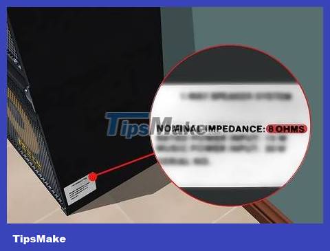
Check the nominal impedance level on the label. Most speaker manufacturers list the impedance level on the speaker label or packaging. The "nominal" impedance level (about 4, 8, or 16 Ω ) is the estimated minimum impedance of most typical audio ranges. Typical sound ranges usually range from 250 to 400 Hz. The actual impedance is quite close to the value in this range, while increasing slowly as the frequency is increased. Below this range, impedance changes rapidly and peaks at the resonant frequency of the speaker with the cabinet.
Some manufacturers use the actual impedance as the nominal impedance parameter on the label.
To understand what these frequencies mean, note that most bass tracks range from 90 to 200 Hz, while sub-drum bass can only reach 20 Hz. Mid-range tones, which include most voices and instruments other than percussion, have frequencies from 250 to 2 kHz.
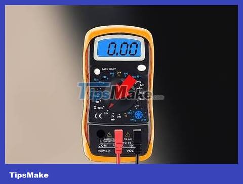
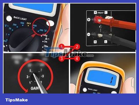
Set the multimeter to resistance measurement mode. The multimeter will pass a small direct current to measure resistance. Because impedance represents the quality of an AC circuit, this method cannot measure impedance directly. However, a multimeter is quite accurate with most home audio setups (for example, you can easily tell the difference between a 4 Ω and an 8 Ω speaker using this method). Before proceeding, you will need to set the multimeter to its lowest range resistance setting (usually 200 Ω for most multimeters). A multimeter with lower settings (e.g., 20 Ω) will give more accurate results.
If there is only one setting for the resistance, this is an auto-ranging multimeter, the device will automatically find the appropriate measuring range.
Too much direct current can damage the speaker coil. This risk is quite low because most multimeters only produce small currents.
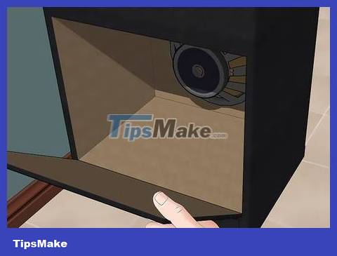
Remove the speaker from the cabinet or open the back of the speaker cabinet. With separate speakers without connections or speaker cabinets, you do not need to disassemble them.
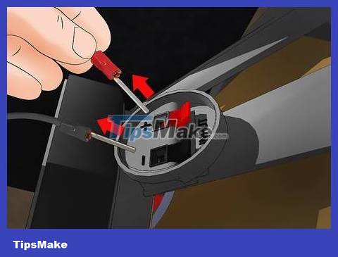
Unplug the speaker. Any current passing through the speaker will cause erroneous measurements, or even burn out the multimeter. You need to disconnect power from the devices. If the wires connected to the terminals are not soldered, remove them.
Do not remove any wires directly connected to the speaker cone.
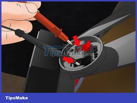
Connect the multimeter's probe leads to the speaker terminals. Observe the terminals carefully to determine which is the positive pole and which is the negative pole. Usually the poles will be distinguished by the symbols "+" and "-". Connect the red probe of the multimeter to the positive terminal, the black probe to the negative terminal.
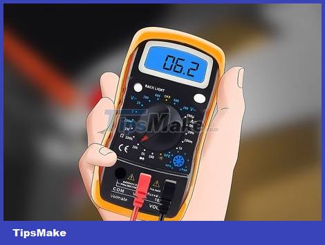
Estimate impedance from resistor. Typically, the resistance rating will be 15% lower than the nominal impedance on the label. For example, it is normal for an 8 Ω speaker to have a resistance of 6-7 Ω.
Most speakers have a nominal impedance of 4, 8 or 16 Ω. After estimating, if the impedance falls within one of these values, you can safely connect the speaker to the amplifier (unless you measure unusual results).
Take accurate measurements
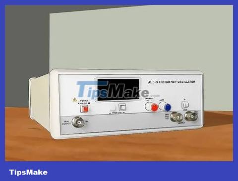
Prepare the sine wave generator. Speaker impedance changes with frequency, so you need a device capable of generating sine waves at many different frequencies. An audio frequency oscillator (or oscilloscope) is the most accurate choice. Any wave generator or pulse generator that produces a strip or sine wave will be effective, but some models may provide inaccurate results due to voltage variations or poor sine wave estimation.
If you do not have experience or only measure at home, a measuring device connected to a computer is the appropriate choice. The accuracy of these devices is not high, but the automatically generated graphs and data will make it easier for beginners to get used to.
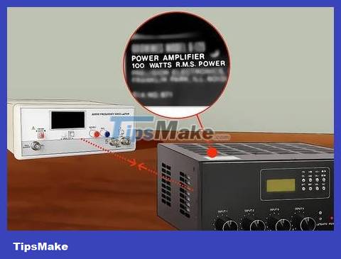
Connect the device to the amplifier's input. Look at the label or specification sheet to determine the RMS (Root Mean Squared: real power or effective power) power in units of W. For this test method, the high power amplifier for give more accurate index.
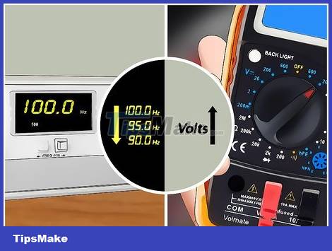
Set the amplifier to low voltage mode. This test method is part of a series of standards measuring "Thiele-Small parameters". All of these tests are designed for low voltage. Therefore, you need to reduce the gain on the amplifier, and set the voltmeter to AC current measurement mode before connecting to the output terminals on the amplifier. The voltage level on the voltmeter should be within 0.5 - 1 V, but if the device is not accurate enough, it is best to set it to the range below 10 V.
Some amplifiers produce inconsistent voltages at low frequencies, which is the main cause of inaccurate measurement results. For optimal results, check the voltmeter to ensure that the voltage is stable as you adjust the frequency with the sine wave generator.
Use a good multimeter if possible. Low-cost models often produce inaccurate results in this test. You can also buy high-quality multimeter probe leads at electronics stores.
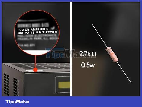
Choose a good resistor. Use the list below to find the resistor with the RMS power level (in W) that best matches the amplifier you have. Choose a resistor with the recommended rating and wattage equal to or higher than listed. The resistance reading does not have to be exact, but if it is too high it can cause the amplifier to malfunction and interrupt the test. If the resistance is too low, the measurement results will be less accurate.
100W amplifier: 2.7 kΩ resistor with at least 0.5 W power
90W amplifier: 2.4 kΩ resistor with at least 0.5 W power
65W amplifier: 2.2 kΩ resistor with at least 0.5 W power
50W amplifier: 1.8 kΩ resistor with at least 0.5 W power
40W amplifier: 1.6 kΩ resistor with at least 0.25 W power
30W amplifier: 1.5 kΩ resistor with at least 0.25 W power
20W amplifier: 1.2 kΩ resistor with at least 0.25 W power

Measure resistance value. This value may differ slightly from the parameters printed on the label. Remember to record the resistance value you measure.
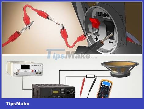
Connect the resistor and speaker in series. Connect the speaker and amplifier with the resistor in between. Thus, the speaker will be supplied with a constant current.
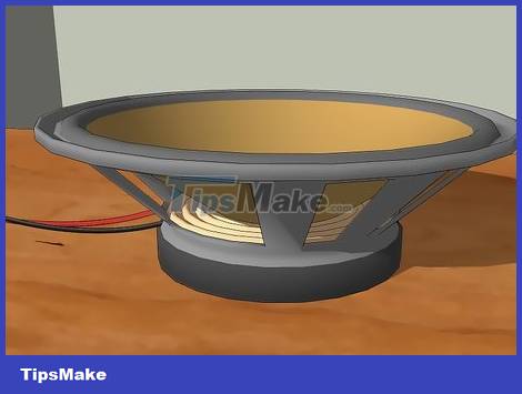
Move the speaker away from obstacles. Wind or bouncing sound waves can also disrupt this precision measurement. At the very least, you should place the speaker in a windless area with the magnet facing down, with the speaker cone facing up. If high precision measurements are required, secure the speaker to an open frame and at least 60 cm away from any solid object.
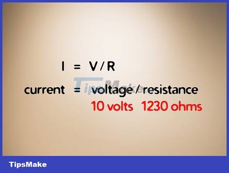
Calculate the current intensity. Use Ohm's law (I = U / R or current = voltage / resistance) to calculate the current and record the results. Substitute the resistance value you measured earlier into the formula.
For example, if the resistance is 1230 Ω and the power supply has a voltage of 10 V, we have a current I = 10/1230 = 1/123 ampere (A). You can keep the fraction as it is to avoid rounding errors.
Adjust the frequency to find the resonance peak. Set the sine wave generator to the mid-range or higher than the speaker's normal usage amplitude (100 Hz is a good starting point for low tones). Connect the voltmeter to the speaker in alternating current measurement mode. Lower the digital stage about 5 Hz at a time until you see a sharp increase in voltage. Vary the frequency up and down until you determine the maximum voltage level. This is the resonant frequency of the speaker in "free space" (the box and surrounding objects will change this frequency).
You can use an oscilloscope instead of a voltmeter. Then, find the voltage with the highest amplitude.
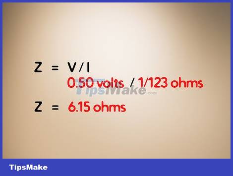
Calculate the impedance at resonance. You can replace the resistance in Ohm's law with impedance Z. We have: Z = U / I is the formula for calculating impedance at the resonant frequency. This will be the maximum impedance of the speaker within the expected audio range.
For example, if I = 1/123 A and the voltmeter measures 0.05 V (or 50 mV), then Z = (0.05) / (1/123) = 6.15 Ω.
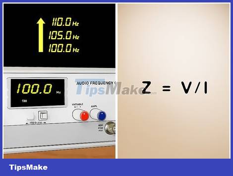
Calculate the impedance at other frequencies. To determine the impedance throughout the speaker's intended frequency range, gradually increase the sine wave in small increments. Record the voltage at each frequency and use the same formula (Z = U / I) to calculate the speaker impedance at different frequencies. Maybe you'll find a second peak, or the impedance will stay relatively stable after you tune away from the resonant frequency.