What is a breadboard and how does it work?
Breadboard is a homemade electronic device, allowing beginners to get used to the circuit without welding. Even seasoned people use the breadboard as a starting point for large-scale projects.
If you are taking the first steps in the DIY world or microcontroller, you may already have a breadboard in the Arduino boot kit or the Raspberry Pi boot kit. Let's see what a breadboard really is, where they come from, and how you can use them through the following article.
What is a breadboard and how does it work?
- What is a breadboard?
- Integrated circuit (IC) and dual inline package (DIP)
- How is breadboard used today?
Source foot
- What if you don't have breadboard?
- Proto-Board and Breadboard
- Printed circuit board (PCB)
What is a breadboard?
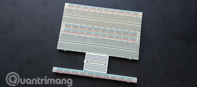
Breadboard is a simple device designed to allow you to create electrical circuits without welding. They come in many different sizes, and the design may also be different, but as a general rule, they will look like this:
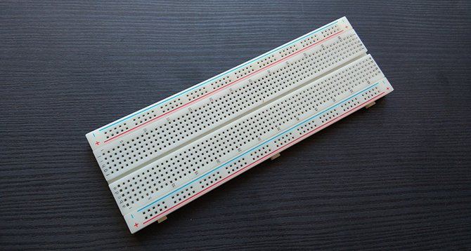
If you have never seen a breadboard before, you may be wondering how to know which hole holds what function. It's a little easier to learn about these holes when you look from below.
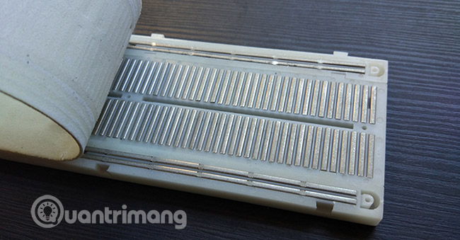
Looking at breadboard from this position will be easier to understand what's going on. Two larger wire sections on each side are often used to connect power to the circuit board. They are often called electric lines. Other small pieces of wire run perpendicular to the circuit board, used for components in the circuit. This chart will help you visualize breadboard from above.
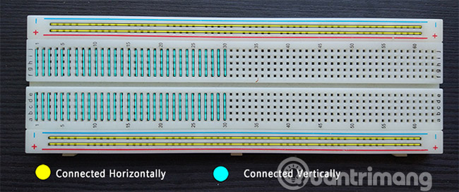
Power lines run horizontally, into 2 rows at the top and bottom.
If you pull any piece of metal out, you will see their use. They are designed to cling to the legs of any part pushed through the holes on the breadboard. This allows you to check the circuit without welding, or circuit connection.
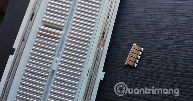
As a general rule, this is how all breadboard works, although they can have many different sizes. Some breadboards have binding posts to power, but it is okay without them. In addition, most breadboards are designed to be connected together, in case you need breadboard for a big project!
Before continuing, you should know that breadboard has another remarkable feature to learn about:
Integrated circuit (IC) and dual inline package (DIP)
Do you see a small gap between the breadboard? That gap is for the integrated circuits!
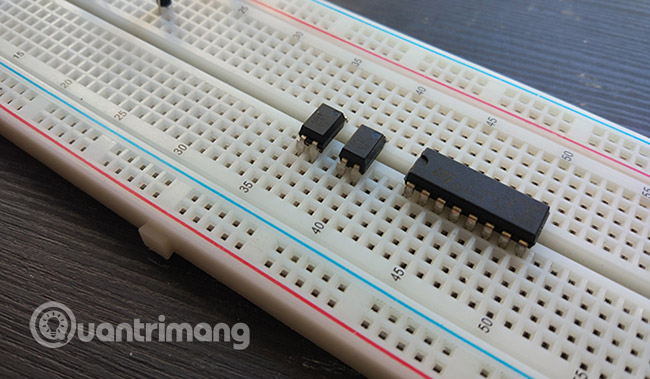
Integrated circuit (IC) is available in most electronic devices. They make engines work, adjust voltages, act as timers, perform logical tasks, and pretty much everything else you need.
The ICs may have different pins, sizes and functions. However, many ICs comply with one standard are called Dual In-Line Packages (DIP) , which means they all share a certain width. That width fits perfectly into the gap between the breadboard. This makes it easier for users to work with ICs, without having to worry about accidentally connecting the wrong pins together.
How is breadboard used today?
In recent years, almost all entry-level electronics (low-level) are related to using an Arduino or a Raspberry Pi.
While there are many things you can do with Raspberry Pi without requiring external components, things get interesting when you use microcontrollers with DIY circuits. Blink sketches for Arduino - usually the first things that beginners do - can be modified to use an LED combination and actual resistor on a breadboard.
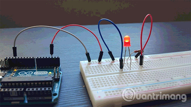
Using what is known, we can see that the wire from Arduino 2's pin enters the power line, before being connected to the positive latch of the LED. A resistor is connected to the negative terminal of the LED, and the other end of the resistor is connected to the ground wire, before returning to the Arduino GND end.
If you want to try it yourself, see the code for the revised sketch at https://pastebin.com/vqXPmPJ4.
Source foot
For simple projects like this, power lines are not always used. But if you need to use many components that all require power, you can supply power from the pins of the Arduino or Raspberry Pi.
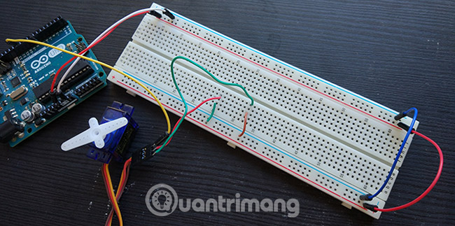
The figure above shows a servo, which requires power as well as instructions from the Arduino. As you can see, the cables from Arduino's 5v and GND pins run to the upper power cord. Then, narrow the gap at the other end to supply power to the lower line, and use small wires to power the VCC and GND wires of the servo. This bridging technique for power lines is a good method, because it ensures components are always accessible to power, no matter where they are on breadboard.
You also use a breadboard in the same way for independent amateur power projects, such as Raspberry Pi builds.
What if you don't have breadboard?
If you don't have breadboard, you can still create simple circuits, but it won't be very convenient.
The method is to use a variation of whether the components are welded directly to each other, or wrap the wire around each leg to connect the components. This method is extremely difficult to use, however, if you must use this method, you can use electrical tape to fix everything in place.
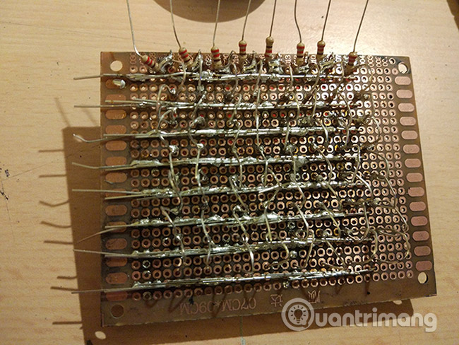
Proto-Board and Breadboard
An easier and longer method is to use proto-board. These circuits are covered in holes with surrounding copper rings, allowing you to create circuits with spot welding components and connect them with wires or additional welding. This is a much more permanent solution and is often used in the end, when you know your circuit will work without any problems!
Printed circuit board (PCB)
A final example is to create your own printed circuit board for a project.
This is a long-term solution, designed specifically for your circuit. Usually, printed circuit board is the last step after testing on both breadboard and proto-board. There are many companies that produce PCBs on order, although you can make them at home, if you want a full DIY experience.
YouTuber Extralife has a video that explains how this process works:
Breadboard is the perfect accessory to learn about electronics at every level.
Even if you are taking the first steps with new projects on Raspberry Pi or Arduino, breadboard is still a great start. Good luck!
See more:
- How to turn the TV into a Retro gaming system with the Raspberry Pi Zero
- How to create an Ethernet crossover cable
- Create your own wireless printer with Raspberry Pi