Power failure still surfs the face roaring thanks to homemade backup charger for Modem
With a backup charger for self-powered mondem from a backup battery for this phone, you don't have to worry about Internet interruption when you have a rotating outage during this hot summer. With the Internet we will have a lot of things to do to help forget the uncomfortable heat of the summer.
- Instructions for making backup batteries from an orange, charging nearly 40% of the battery for iPhone
- Homemade ultra-light light switch, only you can turn it on

The power outage does not affect the Internet signal, so if the Modem is active, you can access the network normally.
For devices that consume less power such as Modem and Wifi Router, only a small power source can be maintained for several hours.

All electronic devices in our family are plugged directly into 220V grid but they only need a DC current with very small voltage usually 9V or 12V. Adapter is a device that turns 220V alternating current into DC current with voltage of 9V or 12V depending on the device.
Thus, we only need a spare phone battery with 1-way current output 5V 1.5A or 5V 2A depending on the type and turn this 5V current into 9V or 12V to supply these devices.

Before embarking on implementation, we should calculate a little about the capacity of batteries and consumer devices so that the product can operate long term and stable.
Physics level 3 formula: P = UI
If the battery has an output power of 5V 2A, the backup charging capacity is 10W.
If the adapter (Modem / Wifi Router) U = 9V and I = 0.6A, the maximum power consumption is 9 x 0.6 = 5.4W (only 60% of the capacity of the backup battery). Thus, backup battery can completely supply power to Router and Modem.
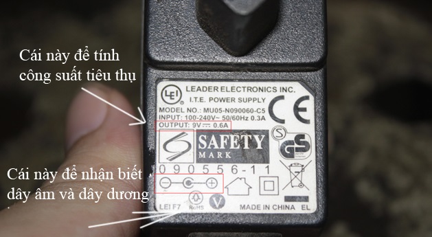
In this article, we'll do a Linksys router using 9V power.
Prepare:
A booster circuit (also called Boost circuit) costs about VND 120,000. You can buy it at electronic parts stores.
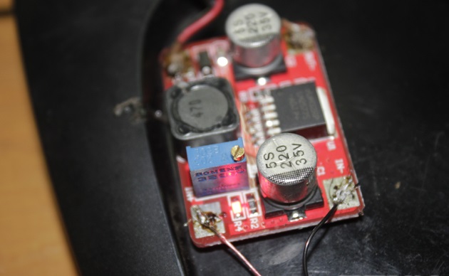
Pressure booster circuit.
A 6-pin power switch, also known as a 3-way switch, is used to switch between "power failure" and "power" modes at VND 6,000. If there is no 6-pin type, you can use 2 3-pin switches as well.
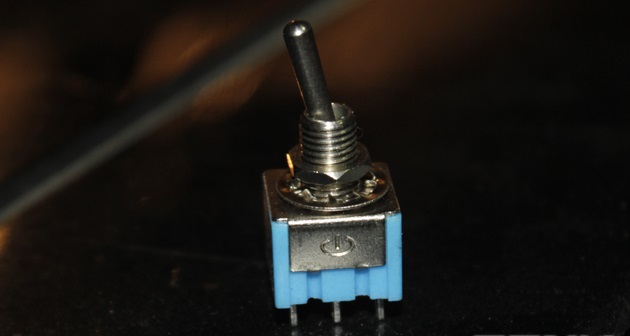
1 USB cable. You can take advantage of extra charging cables.
Common electrical tools such as pliers, scissors, adhesive tape, wires, electric soldering iron, tin etc.
Proceed:
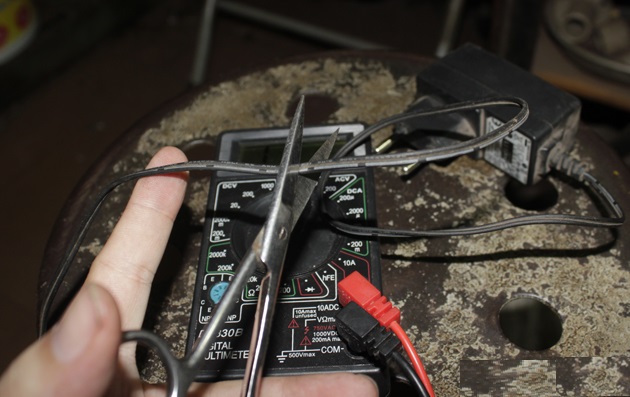
First you need to cut the Modem's power cord in half.

Stripping the end of the rope like the picture.
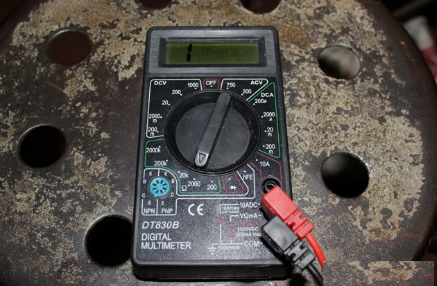
Use an electric meter to determine which is negative, which is anode according to the diagram printed on the Adapter.
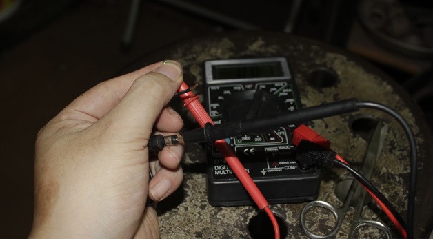
The clock jumps to 0 ie the circuit and that wire is the inner pole according to the diagram.
On the 6-pin switch, determine the position to be welded, so that the left 3 pins only connect negative, 3 on the right with positive wire as shown below.
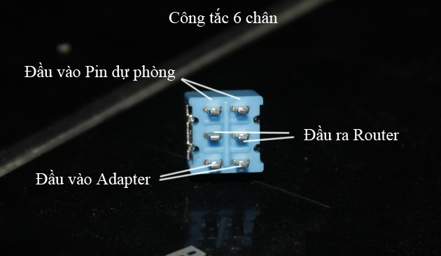
After identifying the locations of the welds, we start welding each wire to the switch exactly as the diagram. Precise welding ensures good contact between work and wire.
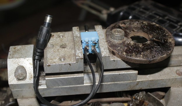
First, we solder the wire to the router first.
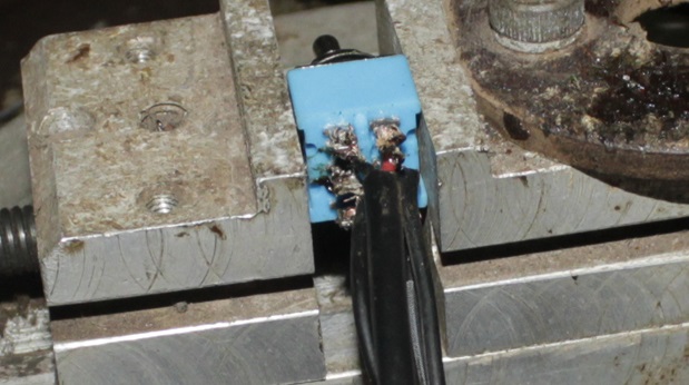
Use 2-color strings to easily distinguish the positive negative.
For the cable that connects from the backup charger to the booster circuit, you should choose a 2-color line to solder to the booster circuit in the right direction. Note that the 2 wires from the switch will connect to the OUT side of the booster circuit.
Cut off the small unused end of the prepared USB cable, peeling off the rubber cover we will have 4 wires are red, white, blue and black.
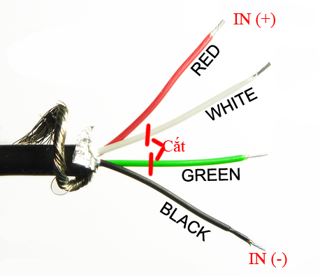
In those 4 strings, we only use 2 black and red wires, so you put 2 white, green strings and cut them.
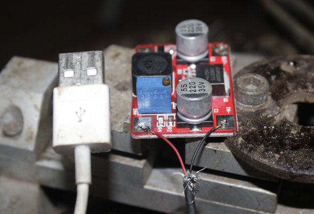
With 2 red wires (+) and black (-) you remove the plastic layer, solder the copper wire to the + - corresponding to the IN side (input) of the booster circuit.
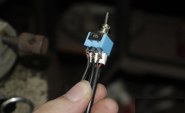
The switch after welding has enough wire, use 1 layer of adhesive tape to move between the legs vertically to ensure the vacuum does not touch each other causing convolution. Then wrap the tape to seal the foot.
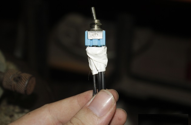
When the power goes out, you turn right, the router will use the backup power. Normally, turn left to get Router to get power from adapter as usual.
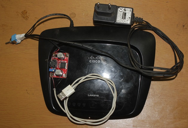
After completing your device will look like this.
With the backup charger just finished, you plug it into the USB without plugging into the router. Pay attention to the blue resistor on the boost circuit with a small screw that will increase or decrease the voltage as you like.
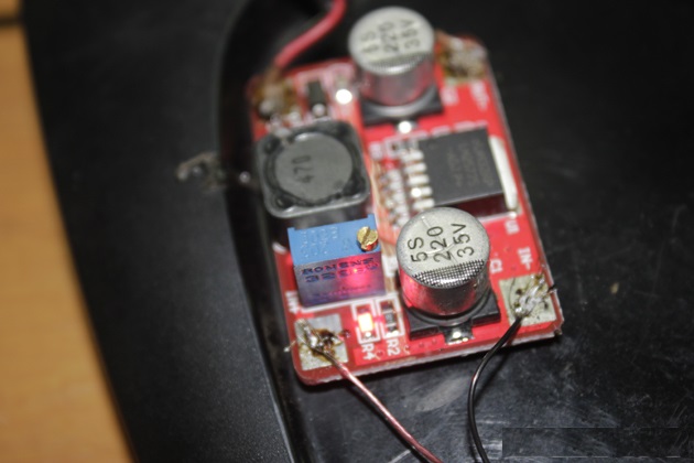
Variable (green) and adjustable screw.
Then you need to use a multimeter to check if the output voltage is correct with the voltage written on the adapter by turning to the VDC scale and measuring the OUT end of the circuit. If the voltage is not correct, turn the screw on the resistor to change the output voltage.
In case you use your own Modem and Router, you need to add 1 more set to maintain both devices.
Note:
In order to backup your phone's battery, you can use the power from the motorbike AC whose voltage is 12V and the maximum current of about 5A to maintain the Modem.
Then, you just connect the cathode directly to the cathode and the anode to the battery's positive anode without the need for an additional circuit, which will work normally. In addition, because the battery's maximum current is very large, you do not need to worry about capacity calculation because at present there are almost no home network devices that consume up to 60W of electricity.
In case, you use battery but Modem only runs at 9V voltage, you need to buy an extra low voltage circuit (BUCK circuit) for about 35,000 VND to lower the voltage from 12V to 9V. The implementation is quite similar to the booster circuit.
You should read it
- ★ How to choose to buy standard backup charger for iPhone
- ★ Tips to fix the errors from the backup battery charger
- ★ Recognize genuine and fake Xiaomi backup battery
- ★ Why can't backup batteries reach 100% capacity as advertised?
- ★ Samsung launches two new backup batteries and car chargers, supporting 'superfast' quick charging